This article, from Railway World, October 1896, describes the recently opened Upper Douglas Cable Tramway.
When describing in our August number the electrical sections of the tramway system of the Isle of Man Tramways Company, allusion was made to the approaching opening of the cable tramway in Douglas, and we undertook to give in a later issue further particulars of this important addition to the company's system. Since then the work has been completed and the tramway opened for public traffic, and we are now able to describe and illustrate the line with some detail. The tramway is the result of a public demand for some means of communication between the Promenade along the shore and Upper Douglas, which was clearly a necessity if the upper part of the town were to enjoy the prosperity and growth to which it might reasonably look forward. Such importance was attached to the construction of a tramway through the upper streets that when early in 1895 the Tramways Company came to the Douglas Town Commissioners to ask for a renewal of the lease of the horse tramway along the Promenade the Commissioners expressly stipulated, as an indispensable feature of the agreement, that the upper part of the town should be directly connected with the landing pier and the promenade by a tramway.
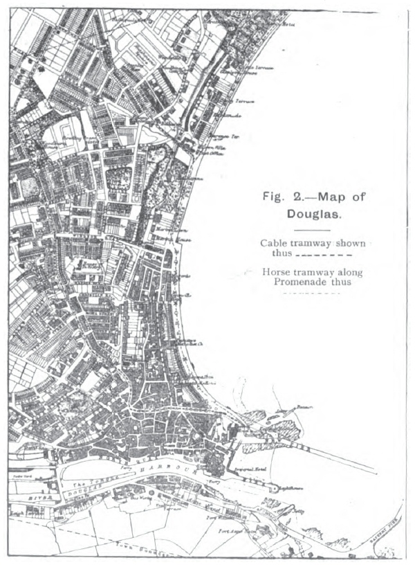
|
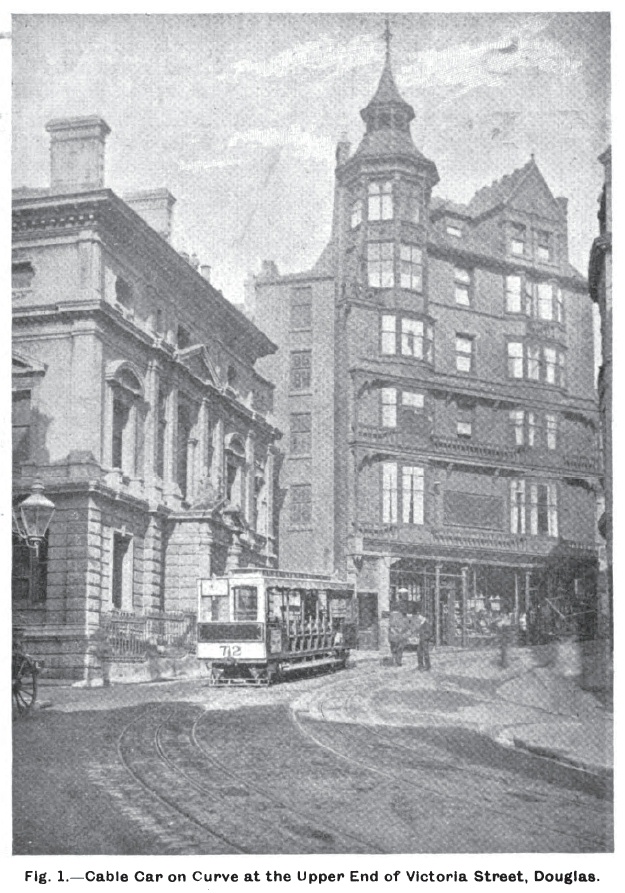
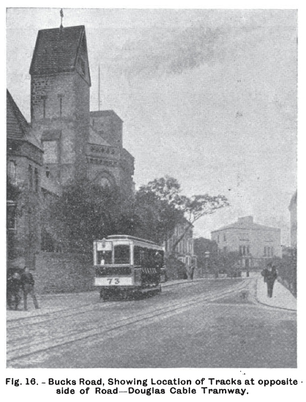
The route as proposed by the Commissioners, and in accordance with which the line has since been laid, commences at the foot of the pier near the southern end of the Promenade, and opposite the Peveril Hotel. From this point it proceeds along Victoria Street, at the top of which it turns sharply to the right up the steep incline of Prospect Hill. The street then curves to the left and some distance further on, by another curve to the right, the tramway is brought into Bucks Road, which is a continuation of Prospect Hill. The route then lies along West View and Woodburn Road, passing several moderate curves until at the northernmost point of the line, Ballaquayle Road is reached. There is a sharp curve here and by a rapidly falling gradient the tram descends to the Broadway, so called no doubt with satiric intent as the street is here so narrow that the double track had to be abandoned and for the remainder of the distance down to the Promenade -- which the tramway reaches near the site of the old iron pier -- there is a single track. The entire length of the tramway between the termini is one and one-half miles, and the total length of the track nearly three miles.
|
As soon as the route was decided upon the tramways company at once recognised that it presented serious difficulties owing to the narrowness of the principal streets through which it would pass, and, particularly, to the severe gradients which formed a large part of the route. The line includes also numerous sharp curves, one of which has a radius of only 40 ft. In certain sections the gradient would be no less than 1 in 10.6, and it was felt that any motive power depending for propulsion on the mere adhesion of the wheels to the rails would be inadequate, probably impossible, and certainly un-economical. In these conditions the cable system alone was regarded as practicable. But before determining to adopt this method a joint deputation of the officials of the tramways company and the Douglas Town Board, consisting of Mr. A. Bruce, chairman of the company, Dr. Farrell and Mr. Callow, directors, Mr. J. Aldworth, manager, and two members of the corporation, visited London and inspected the Brixton and Streatham cable tramway of the London Tramways Company. They then conferred with Messrs. Dick, Kerr, and Company, Limited, the contractors for the London tramway, and obtained particulars with reference to the cable tramways also constructed by that company in Edinburgh and Matlock. On the former the maximum gradient is 1 in 9, and on the latter 1 in 4 1/2, so that the deputation was relieved of any doubt as to the suitability of the cable system for working the proposed route in Douglas. As a result of the investigations of their directors the Isle of Man Tramways Company subsequently entered into a contract with Messrs. Dick, Kerr, and Company, Limited, for the construction of the tramway.

|
Surveys were completed and the necessary sectional and structural drawings were prepared in June, 1895. Originally it was proposed to construct a double track throughout, but to meet the wishes of the Town Commissioners and the Legislative Council, when the Act of Tynwald was procured, the plans were modified, and it was provided that in certain places where the streets were narrow an interlacing track placed in the centre of the roadway should be substituted, the double line being used where the street was wider. This arrangement was found, however, to be unpopular, as it would lead to inconvenience, and eventually an amending Act was obtained enabling the company to follow out the original plans, laying two tracks either in the centre or at opposite sides of the roads as would be most convenient. Meanwhile the line had been constructed as far as possible pending the settlement of the question; but five months had been practically wasted by the delay for which neither the tramway company nor the contractors were in any way responsible; and in May of the present year when the amending Act was passed there were still two and a half miles of line to complete besides a terminal pit. The work was at once resumed, and it was carried out so energetically by the contractors that by the middle of August the tramway was completed.

|
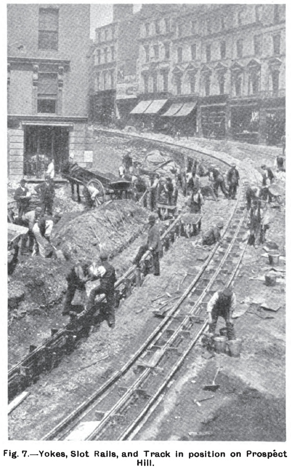
In the construction of the track and conduit the new line resembles closely the cable tramways in London and Edinburgh. The track, which is of 3 ft. gauge, consists of steel rails of the grooved girder type, of the section shown in Fig. 3, and weighing 76 lbs. per yard. Both the cable conduit and the foundation for the track is formed of Portland cement concrete. The conduit is 19 in. deep by 9 in. wide. The cast-iron yokes which support the slot rails have been firmly placed on a foundation of solid concrete, and are spaced 3 ft. 6 in. apart. To these yokes the slot rails, shown in section in Fig. 4 are bolted, leaving an aperture three-fourths of an inch in width for the gripper shank to pass through. The weight of the slot rails is 38 lbs. per yard. The sides of the conduit are formed of concrete in the usual manner. Tie rods connect the yokes with the track rails, and the whole forms a very firm structure of the most durable character. A 6 in. stoneware drain is provided for keeping the conduit free from water, and for this purpose connection is made with the sewers at proper intervals. The entire line and clear-way with a margin of 1 ft. 3 in. outside the rails is paved with granite setts thoroughly rammed and grouted with strong cement in the manner of the best tramway construction. A section of the double track is given in Fig. 5, and the method of constructing the conduit is well shown in Figs. 6 and 7 which are reproduced from photographs taken during the construction of the line up Prospect Hill.

|
|
There is nothing special to be noted as regards the pulleys for carrying the cable in the conduits or in the pits, as the usual methods have been followed. On the straight lengths of track vertical pulleys 12 in. in diameter have been at frequent intervals, their rims being grooved for the purpose, while on horizontal pulleys with flat faces and broad rims have been employed. These pulleys are of the same diameter as the vertical pulleys, but they are placed at varying distances, depending on the radii of the curves. Above each pulley has been placed the usual hatch of tough grey cast-iron, with covers fitted with wooden blocks on the surface as shown in Fig. 9, which represents a longitudinal section of the conduit. The patterns of the pulleys both for straight runs and curves are shown in Figs. 8, 10, and 11. The triangular drawing on the right, Fig. 11, gives the plan of the base supporting the horizontal pulley.

|

|
|
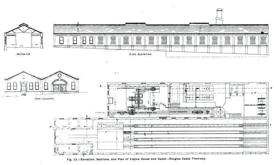
In addition to the pulleys which guide the cable in the conduit there are the large diverting pulleys, 8 ft. in diameter, in the main pulley pit outside the depot and also at the terminal pits at the bottom of the Broadway and opposite the Peveril Hotel near the pier. The entire line is worked by a single cable which passes from the tension carriage along the tension race and subway (Figs. 12 and 13) to the diverting pulley about which it is directed to the left and is carried along the supporting and guiding pulleys to the terminal pit at Broadway. Here it is led around two vertical pulleys each 8 ft. in diameter and then continues up Broadway again, passes the engine house and descends to the terminus opposite the Peveril Hotel. Passing the two pulleys there it is drawn up the hill to the main pit and, being diverted to the right, enters the subway and is taken around the driving pulley to the tension carriage. The arrangements are thus comparatively simple as the cable follows the "Lang" lay principle. It is formed of the very finest steel wire laid on a hemp core, with six strands of thirteen wires each, seven round six. It is 20 tons in weight and is entirely in one length.
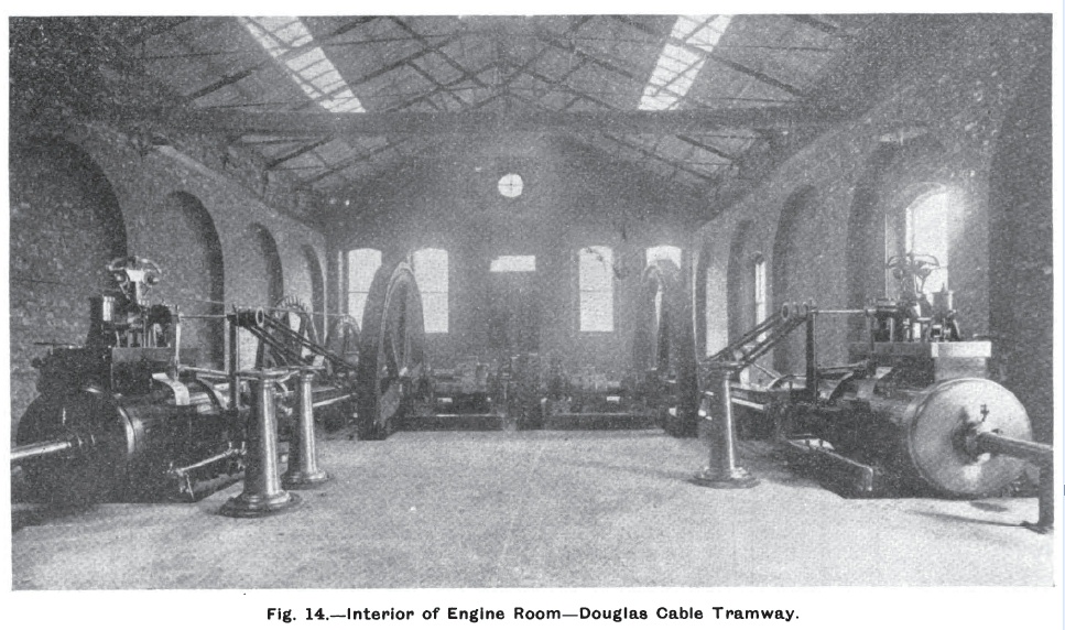
A fine power station has been erected in Ballaquayle Road, near the Broadway, as will be seen from the accompanying plans (Fig. 13). The station is fitted up in a very complete manner, and in addition to the boiler and engine rooms, comprises a reel house, car shed, and various offices. The entire building is substantially constructed of brick, with slate roof, and measures 235 ft. by 74 ft. The boiler house is 11 ft. below the car shed, and 8 ft. below the engine room, with which it communicates by a flight of stairs. Under the firing floor of this room there is an underground storage tank of 6,000 gallons capacity. This is fed from a spring, and a settling tank is used before admitting the water to the storage tank. There is also a blow-off tank, with separate blow-off pipes to each boiler. The reel house, which contains two permanent storage reels for storing cables, is in the rear of the boiler house, and adjoining it under the car shed is a smithy and workshop. The overhead storage feed-water tank with a capacity of 6,000 gallons is also in this room.
|
In the boiler room are two Lancashire boilers, with Galloway tubes. Green's economisers increase the temperature of the water from 60 deg. Farh. to above 300 deg. before it enters the boilers.
The engines, like the boilers, are in duplicate. They are of 250 horse-power each, but one of them is sufficient to work a one minute of service of loaded cars. The engines are of the horizontal high-pressure non-condensing type, with high-pressure cylinders 20 in. in diameter and 42 in. stroke. They are fitted with Dr. Proel's latest patent automatic variable releasing gear and spring governor, which perfectly graduates the output of the engine to meet the varying load on the cables. The exhaust valves are of the Corliss type. The cylinders are steam jacketed with live steam, having drain pipes and automatic traps with connections. The pistons are fitted with Lockwood and Carlisle's patent spring patent. The cranks are of disc pattern, and are fitted with Banjo lubricator and connections for oiling the crank pins while the engines are running. The shafts are of mild steel, 9 in. in diameter, and are fitted at one end with flanged couplings. The flywheels are 13 ft. 4 in. in diameter. The outside of steam chests and cylinder barrel are clothed with non-conducting felt and polished mahogany.
Either engine can be coupled or uncoupled to the crank shafts in a few minutes by means of the flanged couplings. The crank shafts are geared to a counter shaft by means of shrouded double helical spur and pinion gear. The counter shaft carries a Weston friction clutch which works the grip pulley by which the cable is driven. As the cable after leaving the grip pulley is led under an idle pulley placed in front of the grip pulley, the latter is made to hold the cable for nearly three-fourths of the circumference of the grip, an arrangement which gives ample frictional power.
The car shed is 235 ft. in length, and contains four lines of rails, with repairing pits extending the whole length of the shed. Accommodation is thus secured for 21 cars. The cars gravitate into and out of the shed by two curves which form a triangle with the main line as shown in plan in Fig. 12. By means of a traverser the cars can be shifted within the shed without lifting the grippers.
The type of car employed is shown in our illustrations. The car bodies are carried on two bogies, and have seating capacity for 32 passengers. Although provided with windows at both ends, which can be raised or lowered as desired, the cars are open at the sides, and have reversible seats extending across the entire width, the passengers entering from the footboard or long step extending along the sides of the car. Gripper and controlling gear for operating the brakes are placed at each end of the car, and ample room is provided for the gripman, as shown in Fig. 15, which gives a view of a car descending the sharp grade in Prospect Hill. The cars come from the works of Messrs. Milnes and Company, of Birkenhead, and are in every way well appointed. Owing to the numerous steep gradients a special brake working in the slot has been provided in addition to the ordinary wheel brake. Perfect security is thus obtained, as the cars can be stopped almost instantly.

|
With the exceptions noted in the course of description the whole of the works, including engines, driving gear, conduits, and depot buildings were constructed and carried out by Messrs. Dick, Kerr, and Company, Limited, and their chief engineer was responsible for the designs.
On the 6th August the threading of the cable was completed, and on the following day the first car was drawn over a part of the line by the cable. The official inspection took place immediately. Mr. Walker, C.E., the inspector, suggested a slight alteration in the special slot brake to serve some of the curves and, after alarm bells were attached to the cars, a certificate was granted, and the line was opened for traffic on August 15th. Gripper men from London and Edinburgh were specially sent to Douglas to instruct the local men in the use of the gripper and brake mechanism, and in a few days the "probationers" became fully experienced, and were allowed to manipulate the cars without assistance.
|
On August 28th, when the tramway had been in full working order for two weeks, Messrs. Dick, Kerr, and Company, gave a dinner at Douglas to a large number of local gentlemen and others interested in the enterprise. The occasion was rendered specially noteworthy by the satisfaction which the directors of the Tramway Company manifested in their new line. Mr. Alex. Bruce, the chairman of the Company, said that the tramway had already a traffic far beyond their expectations. Four to six thousand persons had been carried each day, and not a single accident or stoppage had occurred on the cable section. Referring to the construction of the line, Mr. Bruce spoke in the most enthusiastic strain, and complimented the contractors in the warmest manner on the admirable way in which the whole work had been carried out
Go to top of page.