|
THE WIRE ROPE STREET RAILWAYS OF SAN FRANCISCO, CALIFORNIA. By A. S. Hallidie |
August 2, 2003 marked the 130th
anniversary of Andrew Smith Hallidies
successful test on San Franciscos Clay Street hill of the cable car or as
commonly referred to at the time "wire rope street railway." Hallidie
himself authored this piece about San Franciscos "wire rope street rail ways"
that was published in the Scientific American Supplement, September 17,
1881. Hallidie provides a detailed description of the operation of his
Clay Street Hill Railroad. He
notes that the concept of the cable car has been employed by other San
Francisco companies, such as the Sutter Street Railroad
and the California Street Railroad, with significant
positive economic results. He fails to
mention the legal battles between himself and the other San Francisco
cable car entrepreneurs over his cable car patents. In conclusion Hallidie
notes, after arguing the cable car is suited for all types of climates,
that The Traction Railway Company of San Francisco (his company) has
control of this system of street railroading. One cannot help but wonder
if this article was part of a Hallidie marketing campaign to earn
royalties. This was the era before the perfection of the electric
streetcar. The competition the cable car faced -- the horsecar and steam --
had limited suitability.
Introduction
by Walter Rice
Thanks to gripman Val Lupiz for locating and providing this important historic piece. The article was scanned and transcribed as it appeared in 1881. It reflects a style of writing and use of grammar that was in vogue during that period. WER

This system
of street railroad, the invention of Mr. A. S. Hallidie, was put in use by
the Clay Street Hill Railroad Company, in the City of San Francisco,
California, August, 1873, since which time it has been constantly running,
and has been found to answer all requirements, and to exceed the
expectation of engineers and others who had examined the plans of the
inventor; and has been adopted by other companies in San
Francisco.
It is adapted to all kinds of metropolitan railroading, where the surface of the streets has to be kept free from obstructions, where locomotive steam engines are not permitted, or where the streets are so steep as to make the use of horses difficult or impossible.
 The system consists of
an endless wire rope placed in a tube below the surface of the ground,
between the tracks of a railroad, and kept in position by means of
sheaves, upon and beneath which the rope is kept in motion by a stationary
engine, the power being transmitted from the motor to the rope by means of
grip or other suitable pulleys, and from the rope to the cars on the
street by means of a gripping attachment fixed to the car by a steel bar,
and which posses through a narrow slot in the upper side of the
tube.
The system consists of
an endless wire rope placed in a tube below the surface of the ground,
between the tracks of a railroad, and kept in position by means of
sheaves, upon and beneath which the rope is kept in motion by a stationary
engine, the power being transmitted from the motor to the rope by means of
grip or other suitable pulleys, and from the rope to the cars on the
street by means of a gripping attachment fixed to the car by a steel bar,
and which posses through a narrow slot in the upper side of the
tube.
It presents no impediment to ordinary travel. The rope is grasped and released at pleasure by a peculiar gripping device attached to the passenger car, and controlled by a man in charge. The car is more smoothly started than by horses, and instantly stopped on any part of the road; its mechanical construction is simple and easily controlled, and on the streets it does not frighten horses or endanger lives.
A description of this system, as in use by the Clay Street Hill R. R., of San Francisco, will best explain the modus operandi.
Clay street is a central street in the City of San Francisco, and for a number of blocks near the lower terminus the road is very densely populated: the street is only 49 feet wide from house to house, and between the sidewalks is occupied by two lines of gas pipe, one line of water pipe, a street sewer, and at the cross streets by water cisterns.
The lower terminus of the road is at the intersection of Kearny and Clay streets. The summit of the hill is 307 feet above Kearny Street. The incline on Clay Street has a double track, and is 5,197 feet long; the rope runs into the engine house at Leavenworth Street. The ascending grades are as follows: From Kearny to Dupont, 45 fcct; from Dupont to Stockton, 45 feet; from Stockton to Powell, 62 foot; from Powell to Mason, 42 feet; Mason to Taylor, 48 feet; from Taylor to Jones, 67 feet. Then the grade descends, as follows: Jones to Leavenworth, 15 feet; Leavenworth to Hyde, 50 feet; Hyde to Larkin, 50 feet; Larkin to Polk, 45 feet; and then an ascent of 15 feet from Polk Street to Van Ness Avenue. The distance between each street is 412½ feet. Clay Street runs at right angles to the above streets, which have widths varying from 45 feet to 68 feet 9 inches. All the street crossings are level. The steepest grade is 1 in 6 15/100.
The general arrangement of the system in use by the Clay Street Hill Railroad is as follows:
An endless steel wire rope, three inches in circumference, 11,000 feet long, is stretched the whole distance, lying in iron tubes, supported every 39 feet on 11-inch sheaves. This rope is supported at every change of angle at the lower crossings on sheaves four feet in diameter passing around a horizontal sheave eight feet in diameter at the lower end of the line, and at the engine house around two angle sheaves, each eight feet in diameter, which lead the rope on the grip pulleys, also eight feet in diameter which are driven by one 14 x 28 engine. The steam is furnished by one boiler 16 feet x 54 inches, using 3,700 pounds of coal per day. They have also duplicate engine and boiler, which are held in reserve.
The patent grip pulleys, being furnished at their circumference with jaws that grip and release the rope automatically by pressure of the rope in the jaws, prevents the rope from slipping; and being set in motion by the engine actuates the endless rope, while traveling up one tube and down the other.
In addition to the sheaves that support the rope in the tubes, at the upper side of each crossing, where the incline makes an angle upward, there are sheaves in the tubes that keep the rope down and from striking the upper part of the tube.
It will be understood that there is an opening in the upper side of the tube. This opening runs the entire length of each tube, forming a long slot seven-eighths an inch wide. This slot is not immediately over the center of the tube, but on one side, to keep sand and dirt from falling on the rope, to clear the upper sheaves, and enable the foot of the gripping attachment to pass by and under the upper sheaves, and over the lower sheaves in the tube.
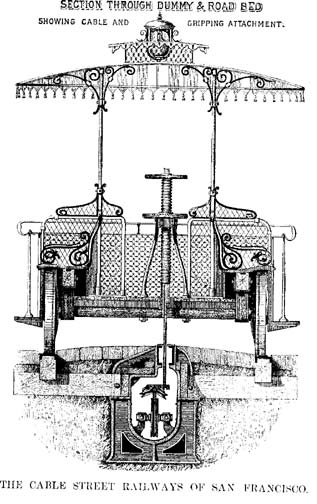
The connection between the cars on the street and the traveling rope is made by means of this gripping attachment, which is hereinafter described. The cars are made to seat 14 passengers, and the dummy 16, but not seldom as many as 44 have ridden in the car, and 26 on the dummy -- 70 in all; and the roads with broad gauge, larger cars, and more even grades have, in one load on car and dummy, carried as marry as one hundred and sixty passengers. It is true, they were crowded, but this is always the case on holidays. The traction car, or "dummy," with the gripping attachment, is attached to the passenger car firmly, so that there can be no danger of accident. The passenger car is amply provided with brakes. In addition to the usual car brake, there is another attachment operated in the same manner as ordinary brakes, which forces a broad band of wood down on each track immediately under the car. This arrangement is shown in our first engraving. Strong iron drags are provided, so that if an accident should occur in going up the hill, they will immediately catch in the street, and prevent the car from going backward. When it is necessary to back down hill, these drags are raised up out of the way by the conductor.

The "dummy" is also provided with powerful brakes. The "dummy" and car are connected with a suitable coupling, so that the weight of the car going down comes on the rope and is utilized to draw up the other cars on the other track. The brakes are not usually employed when coming down, except when it is necessary to stop, as the car runs down with the same speed as the rope, as long as the gripping attachment is in connection with the rope.
By referring to the engravings, the system will be more clearly understood. The first engraving is a side view of road and car and dummy; the tube is in longitudinal section and shows the arrangement of the rope; the upper pulleys for keeping the rope down where the grade changes upward, and the lower or supporting pulley, also the gripping device attached to the dummy and to the rope.

We have an isometrical view of the road-bed -- portion of the tube being removed to show the gripping device attached to the rope; the lower end of the shank is only shown (being broken off in the drawing), being sufficient for the purpose; the construction of the tube and the tube frames clearly shown, and the appearance of the rails and slot and surface of the street when paved.
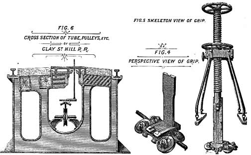
The patent gripping attachment in two different positions is shown. A vertical slide works in a standard, and is moved up and down by a screw and hand wheel. This screw is shown on the cut of dummy and road-bed. The small upper screw going down through the large screw operates it. At the lower end of this slide is a wedge-shaped block. The wedge actuates two jaws, horizontally, which open and close according to the direction in which the slide is moved, closing when the slide is moved upward. These jaws have pieces of soft cast iron placed in them, which are easily removed when worn out. These pieces of iron are of proper shape and size inside to grip the rope when they are closed over it.
On both
sides of these jaws, and attached to them, are two small sheaves. These
sheaves are held by means of rubber cushions, sufficiently in advance of
the jaws to keep the rope off from the jaws, and at the same time to lead
the rope fairly between them, allowing it to travel freely between the
jaws, when they are separated, without touching them. When it is required
to grip the rope, this slide is drawn up by means of the small screw
before described, and the wedge at the lower end closes the jaws over the
rope, at the same time forcing back the small guide sheaves on to the
rubber springs.
The standard containing the slide, etc., is enclosed and retained in an iron bracket, shown on the dummy, and raised and lowered bodily through an opening in the tube from above the surface of the street to the rope in the tube by means of a screw and nut with hand wheel attached. The iron bracket is secured to a skeleton or traction car called a dummy, as shown in first engraving. The dummy is coupled to the passenger cars, at the bottom of the incline, and uncoupled at the top, and vice versa; horses can then be coupled to the car if desired. As before stated, the rope is constantly in motion, running between sheaves placed in the tube. The slot of the tube is on one side of a vertical line drawn through the center of the tube; and referring to Figs. 4 and 6, it will be seen that the foot of the gripping attachment projects on one side, giving it an L shape, enabling the jaws to pass under and over the rope sheaves in the tube. In order to stop the car, the jaws of the gripping attachment are opened slightly; when they release the rope, the guide sheaves take it, and the car stops.
The shank of the standard containing the slide, which works in the slot of the tube, is one half of an inch thick and 5½ inches wide, there being one eighth play on each side; all the essential parts of the gripping attachment are made of steel.
The rope runs 17½ hours per day, at a speed of 6 miles per hour. The cars start every five minutes, except in the afternoon, when they start every three minutes.
The road has a gauge of 3 feet 6 inches. An ordinary 30 pound steel T rail is used on Clay street, which is set flush with the street and presents a neat, smooth appearance. The stretching arrangement at the lower end has a counter balance of 3,300 pounds weigh on a double purchase, which keeps a constant strain on the rope under all circumstances.
This machinery so arranged that the wire rope passes for some distance in open view of the engineer, so that it can readily be examined at any minute.
The hill is the best portion of the city for residences, and the road brings within five minutes of the business portion of the city a large amount of property that was comparatively worthless on account of the difficulty of access, but is now much sought after, having trebled in value since the road was completed.
After the Clay Street Hill Railroad had been running three years and a half, and the economy and practicability of the system was thoroughly tested, the Sutter Street Railroad Company, whose lines bad for many years been unprofitably worked by horses, changed their system from a horse road to the wire cable system; and by the end of the year 1879 had reconstructed nearly their entire road on this system. This company has now 16,000 feet (over 3 miles) of double track operated on this system. The gauge of the road is 5 feet, and its greatest elevation is 167 feet above its initial point.
The California Street Railroad commenced running April, 1878. Its length is 12,000 feet, and it passes in that distance over two elevations, the heights being 265 feet and 235 feet above base respectively, the valley between being 125 feet above base. The gauge is 3½ feet, same as the Clay Street.
The Geary Street Railroad runs over a comparatively level street and through the most central and populous streets of the city. It was completed and commenced running March, 1880.
All these roads
are working successfully, and carry in the aggregate about 35,000
passengers daily, at a uniform fare of five cents.
Several other
roads are projected on this system, among which the Presidio Railroad
Company has commenced work, and will be two miles long when completed. It
ascends a hill 246 feet above its initial point. The estimated cost of
constructing this road, which is five foot gauge, double track, runs over
high hills and much of it through hard rock, is two hundred and ten
thousand dollars. This includes lot, engine house, all the machinery, road
bed, cars, and full equipment throughout. Of course, in other cities where
material and labor are cheaper and ground more favorable the cost would be
much less.
Although this system was first adopted on roads where the grades are too steep for horses to work to advantage, the economy of its working has so demonstrated itself that all the level roads in San Francisco have obtained amended charters giving them the privilege of turning their horse roads into rope roads. The wear and tear on the streets, as well as the accumulation of filth due to horses, is entirely avoided. Humanity is not shocked by the overloading of street cars or the overworking of horses.
In cities where the severity of winter closes traffic for days at a time, this system can keep its own tracks clean by a cheap system of warming the tube, and by the great traction power of the rope on snow plows and scrapers -- a power which it is impossible for horses to produce struggling through the frozen and snow covered tracks.
The saving effected by the employment of this system from thirty to fifty per cent, on that of horse roads, while its capacity for traffic is almost unlimited. The speed at which the car travels is from six to eight miles per hour. The Traction Railway Company of San Francisco has control of this system of street railroading.

Return to the San Francisco page.
Go to top of page.
Home/ What/ How/ Where & When/ Who/ Why
Chronology/ Miscellany/ Links/ Map/ Bibliography
Introduction Copyright 2004 by Val Lupiz, Walter Rice. All rights reserved.
Last updated 01-Oct-2004