This article, from The Street Railway Journal, September, 1892, describes the completion of Washington, DC's Washington and Georgetown Railroad cable lines.
The Washington & Georgetown Railroad Co.'s System Completed.
On August 6, last, just two years from the date of the passage of an act by Congress requiring that within two years the two principal railway companies in the city of Washington equip their lines for mechanical traction, the first cable train was run over the Pennsylvania Avenue division of the Washington & Georgetown company's system. Within a week twenty trains were running, and before this paper reaches our readers all the horses will have been withdrawn and the entire system, embracing twenty-two miles of track, will be operating by cable. The company, and especially its president, Mr. Henry Hurt, the engineers and contractors are to be congratulated on having completed their Herculean task on time and in so creditable a manner. All parties engaged in the work must certainly experience a thrill of satisfaction in having been the agents for the construction of such an admirable system.

|
FIG. 1. -- CABLE SYSTEM OF THE WASHINGTON & GEORGETOWN RALWAY CO. |
The accompanying diagram (Fig. 1) gives an excellent illustration of the relation of the different lines, embracing the system and their location with reference to the public buildings. The Seventh Street line (seven miles), it will be remembered, has been in operation about two and a half years, and it was the success had with this line that determined the company to cable the entire system. The new construction, therefore, embraces fifteen miles, and, as above stated, has been completed within the last two years.
|
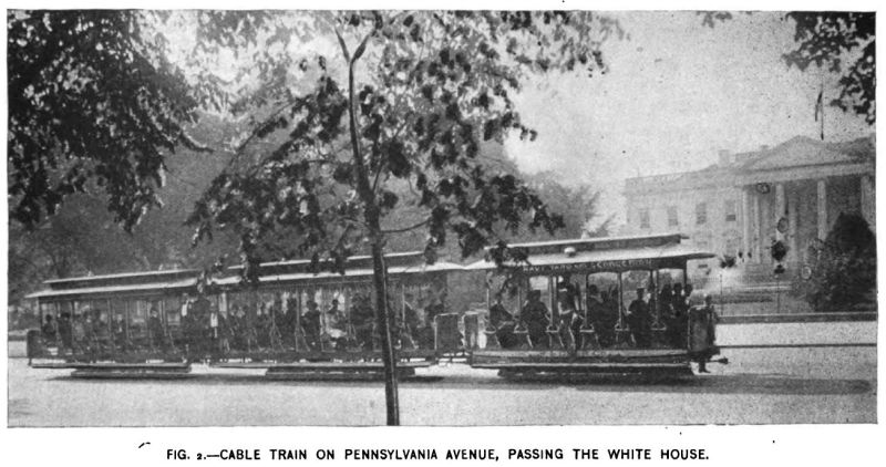
The character of the street construction was illustrated and described in our December, 1891, issue, where it was stated that the track consisted of an eighty pound, Johnson girder, grooved rail of the English type. With such a substantial construction and the streets paved with asphaltum flush with the rail, a ride along the avenue in one of the handsome trains of open cars (Fig 2) gives one a sensation more nearly like the floating in a boat upon a placid lake than we remember to have found on any other line.

|
The power house, which is to operate the new lines, and which we have before illustrated, is a handsome six story brick and iron structure, 190 x 240 ft. and 100 ft. high, on ground occupying an entire block facing on D Street a short distance from the avenue. The power house occupies the rear of the ground floor, and the company's offices, the first two floors, front to the right of the main entrance. The upper stories will be leased for manufacturing purposes. The building is constructed with a large open court above the first floor which is roofed with skylights, thus admitting light to the tension and engine rooms. The engine and driving drums (Fig. 3) occupy a large, high, light and airy room handsomely finished, being ceiled overhead with Georgia pine, and the side walls wainscoted to a height of five feet with the same material, but above finished with white Keen cement. The floor is of white maple in narrow strips, and the iron columns are to be encased in terra cotta, terminating in a handsome capital of the same material and protected for about four feet above the floor by a bronze base. On one side opening out from the company's offices is a visitors' gallery, having swelled fronts or bays, and ornamented with a wrought iron guard with a brass railing.
The two engines are of the Reynolds-Corliss type, 750 H. p. each, with 36 X 72 in. cylinders, and were manufactured by the E. P. Allis Co., of Milwaukee, Wis. From the centre of the crank shaft to the rear end of the cylinder head, the engines measure thirty-two feet, The engines are coupled to either end of the main shaft which is sixty-six feet long and fifteen inches in diameter. Each cable drum of a pair is driven independently from the same pinion by means of two-inch Stevedore manilla rope. This is a new departure in cable driving, being the first power plant equipped in this manner, and so far is working in a very satisfactory manner. The three rope pinions are nine feet eight inches in diameter, and are each operated by means of a Weston-Caperon clutch. The rope pulleys are each twenty-six feet in diameter, and the centres of the shaft of each set are distant from the main shaft centre, respectively, thirty and forty-seven feet. To compensate for any inequality in the drive, two more ropes are used on the short centres in each set, and two sets have nine and seven ropes respectively, while the third has fourteen and twelve ropes.
The winding drums are fourteen feet in diameter and are of the differential ring type, having been manufactured by the Walker Manufacturing Co., Cleveland, O., which company also manufactured the tension carriages and elevating sheaves and frames. There are three sets of winding drums, each making 18.56 revolutions per minute and giving to the ropes a speed of nine miles per hour. The three ropes are of the following length: That on the Navy Yard division, 31,435 ft.; the one on Fourteenth Street, 27,699 ft., and the Georgetown division 23,468 ft. There is also a fourth rope, 3,822 ft. in length, which operates a branch line to the Baltimore & Ohio Depot, and which is driven by a set of auxiliary machinery located in a pit at the foot of the avenue near the Peace Monument, and operated by power transmitted from the Navy Yard or New York Avenue rope.

|

|
Fig. 4 is a plan of the auxiliary drive, from which it will be noted that the return rope from the Navy Yard passes around a large sheave to the left, then back and around a horizontal driving sheave, having upon its axle a smaller two grooved winding drum, by means of which the auxiliary rope is moved at a slower speed. The auxiliary rope also passes over a one grooved idler, and from the drivers to a tension carriage (Fig. 5) anchored by a heavy spiral spring and located in a second pit beneath the track some distance along the avenue, but connected with the first by a low tunnel. Two of the ropes were manufactured by the John A. Roebling's Sons Co., one of them being of the Lang lay type, the other made by the Broderick & Bascom Co., St. Louis. The ropes from the power plant are led out on the Fourteenth Street side, where they are deflected around twelve foot sheaves mounted in U frames along the street to a second pit located at the avenue. Both west bound ropes are deflected towards Fifteenth Street and pass the Treasury Building, where they separate, one going to Georgetown the other out Fifteenth Street. The lines, it will be noted from Fig. 1, have a large number of curves, there being about 5,200 ft. of curve construction; but all the curves are of compound type with the smallest radius not less than sixty feet.

|

|
The curve pulleys (Figs. 6 and 7) are two feet in diameter and have no bottom flange, the rope being held in place by carrying pulleys placed between the curve pulleys. They are mounted in adjustable frames, their position with reference to the slot being regulated by set screws. The wheels turn on a fixed spindle which is provided with a gun metal washer on which they rest. The bearings are lined with babbit, and the spindle has an oil passage drilled as shown, with an oil cup attached to the top.
The carrying pulleys are of cast iron with a chilled face, and are about fourteen inches in diameter. The arms are cast very dishing to prevent shrinkage checks. They are pressed on a plain steel spindle and mounted in self-centering babbit bearings enclosed in a grease cup with a leather lined cover. The box contains a wooden thrust block and dust collar. This type of sheave has been adopted in preference to the wrought iron arm pulleys used on the Seventh Street line. The wrought spokes frequently became loosened and rendered the sheave unserviceable.

|
The boilers are eight in number and arranged in two batteries, one of which is shown in Fig. 8 and are each 184 H. p., and were manufactured by the Babcock & Wilcox Co. The same type of boilers is employed in the Seventh Street station and they have given excellent satisfaction. The boilers are equipped with the Roney mechanical furnaces which are operated by a Westinghouse compound engine, and which were installed by Westinghouse, Church, Kerr & Co., of New York, who also supplied the separator or steam loop in the vertical steam pipe above the engine shown in Fig. 3. The coal is elevated to storage bins and is delivered by gravity to the furnaces. The cinders are drawn directly into a tram car located beneath the boiler room floor, and are then elevated and run out into wagons. The additional steam equipment consists of an 200 H. P. Berryman heater, two Deane duplex feed pumps, while all pipes are provided with Chapman valves of the latest patern.
|
|
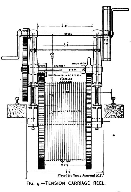
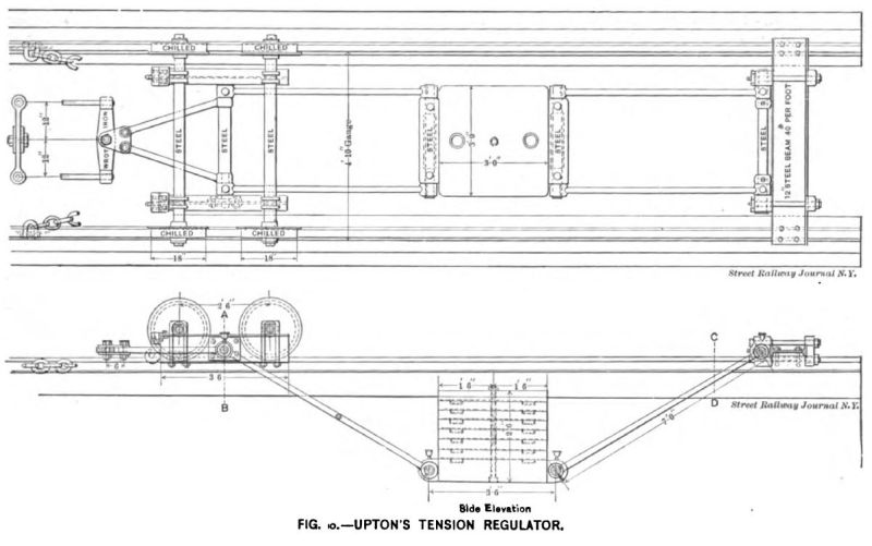
The tension carriages (Figs. 9 and 10) have several novel features. The reel mechanism or winch of the carriage proper is provided with a rope drum in place of a hand crank, upon which several turns of one inch manilla rope are wound. The end of this rope, being made to wrap a capstan on the end of the revolving shaft, which transmits power to winch reel and hauls the carriage back, thus taking up the stretch of the rope. The tension weight is hung by means of a second carriage and anchorage as shown in Fig. 10. This method of attaching the tension weight was devised and patented by Mr. W. B. Upton, chief engineer of the company, and has been working for some time at the Seventh Street power house in a very satisfactory manner. From the illustration it will be seen that the weight is graduated automatically according to the strain on the rope, two carriages being connected by wire ropes.
In addition to the power equipment for working the lines, there has been installed another 250 H. P. Reynolds-Corliss engine for supplying power to the tenants. Rope belts will be employed for transmitting power to the different floors, which will operate in a vertical shaft directly above the driving drum which has grooves for forty-eight three-quarter inch ropes, the intention being to lead a set of ropes out at each floor according to the power required.
Another novel feature about the power house is the drainage system. The basement floor being located, as we have noted in former articles, below tide water and several feet below the city sewers, some means of getting rid of the seepage water was necessary. Accordingly a number of iron tanks were sunk, to which sub-drain pipes were led and which deliver all the water to the tanks, from which it is lifted and discharged into the sewers by means of Shone pneumatic ejectors, manufactured by Hughes & Lancaster, Chester, Pa. The compressed air for operating the ejectors is provided by a small air compressor located near the engine room. The sanitary pipes of the building lead directly into the sewers, so that only the surface water reaches the seepage tanks.
The new car equipment of the line consists of seventy grip cars, manufactured by the John Stephenson Co., Ltd., and 180 twenty-two foot open cars, manufactured by the American Car Co., of St. Louis. Contracts have also been let for ninety-two box cars. All the cars are equipped with the Baltimore running gear, furnished by the Baltimore Car Wheel Co., and the grip cars are provided with track brakes. That these cars are a credit to the manufacturers as the train illustrated in Fig 2 will show. The California or Root type of grip is employed, with certain improvements and modifications. Fifty trains of two or three cars will be run according to the demands of traffic. A three minute headway is maintained on the Georgetown and Fourteenth Street divisions, and as all trains run on the avenue this will give a minute and a half service on this line to the Peace Monument, where the trains again divide and go a part to the Navy Yard and a part to the Baltimore & Ohio Depot.

|
Fig. 11. illustrates the crossover switch at the Georgetown terminal. There being a slight grade to the west the grip drops the trailers as it approaches the first switch and passes along on the straight track to a point between the two crossovers. The train is then run by gravity over the surface crossover, the grip car takes the cable for a short distance and shuts over and couples to the other end of the train and starts out on the straight track. This arrangement requires bur one grip car at the terminals, and an extra grip is not kept in waiting as on the Seventh Street line.
The ordinary gypsy pickups are provided at the terminal switches, but at the crossing at Seventh Street and at the branch switches the rope is automatically replaced in the grip by a new gypsy recently devised by the chief engineer and which is working very satisfactorily.
Nearly all the special iron work required in the construction of the line has been gotten out in the company's own shops. One of the old stables near the foot of Seventh Street was converted into a machine shop and equipped with steam power and a complement of iron working tools. With this equipment the switches and crossings have been gotten out, the carrying and curve pulleys bored, frames drilled and fitted, and the grips (over 150) made.
Besides the power house above described, the new equipment includes two commodious car barns, one near the Navy Yard terminal, with a capacity for 150 cars, and one at Mount Pleasant near the Fifteenth Street terminal, having a capacity for 300 cars, which we have before illustrated. These buildings are handsome brick structures and are provided with all modern conveniences, including a steam equipment for operating the car elevators and electric light plants. The receiver's room, waiting room, conductors' and drivers' rooms are nicely furnished and provided with lockers and elaborate sanitary arrangements.
The entire cost of the system, including the buildings, has been about $3,500,000. Exclusive of the buildings and rolling stock, the lines have cost about $100,000 per mile of double track.
The chief enginer of the company, Mr. W. B. Upton of Kansas City, designed all the plans of the road, and has frequently been on the group to watch the construction and in consultation with Mr. D. Bontecou, the consulting engineer of the company, of Kansas City, but the execution of the work has mainly been under the direction of Mr. David S. Carll, to whom and the the contractor, Mr. E. Saxton, great credit is due for the substantial character of the work and the successful manner in which the lines are operating. Mr. Walter C. Root, of Kansas City, was the architect of all the buildings.
The contractors for material and work, other than those already named, were The Chapman Iron Co., of Kenton O., iron work on power house: Pennock Bros., of Philadelphia, general contractors of power house; Pullman, of Kansas City, power house foundations; C. W. Hunt Co., New York, manilla rope belts ; Steadman Foundry, Aurora, Ind., carrying pulleys and boxes; Chester Steel Castings Co., Chester, Pa., grip castings; General Electric Co., all the lighting; Smith & Vaile Co., Dayton, O., yokes, etc.; J. L. Parsons, Washington, D. C, contractor Mt. Pleasant car house; S. H. & P. F. Adams, Navy Yard car house; Thos. C. Bosshor, of Baltimore, steam heating.
Go to top of page.