This article by Samuel Diescher, from Cassier's Magazine, June, 1897, describes the typical inclined planes, urban funiculars, in the US. He does not mention that he designed and built many of them.
By Samuel Diescher.
INCLINED planes were known probably as long since as mining was pursued in a rational and extensive manner, and were used to lower the products of mines, situated on elevations, to the roads, rivers and mills in valleys. To-day scores of them can be seen in action along the slopes of the river valleys of the bituminous coal regions of Pennsylvania and West Virginia in the United States. But it is of comparatively recent occurrence that they were employed also in the transportation of people, teams, electric cars, etc.
The inclines found about mines, as a rule, are so-called "gravity inclines," which designation is derived from the fact that they are operated by the force of gravity, being employed not to raise, but only to lower, a load, whereas those in passenger and other service chiefly referred to in this article, are operated by power plants especially constructed for this purpose. Most of the inclines of this latter type are located at Pittsburgh, Pa., and Cincinaati, O. The reason for their existence and popularity there is that both cities are hemmed in by a crescent of hills, and the area for building purposes is not very extensive. Both of these cities have so grown that most of the ground on the lower levels has been taken up by commercial and industrial establishments, and since ground, demanded for such purposes, commands a higher price than could be obtained for it if used for dwelling purposes, people in search for building sites had to look beyond the business portions of the cities for them.
The hills surrounding Cincinnati are on the average about 300 feet above the general city level, and those at Pittsburgh are about 400 feet high, and in both cities large areas of moderately rolling ground are found on these hills, admirably adapted for residence sections of large centres of population. In both cities the higher sections are accessible by way of circuitous roads, but their grades are too steep, as a rule, for foot travel, and rides on them, for same reason, are too tedious to be pleasant. This, with the difficulty of transporting large crowds almost simultaneously during the morning or evening hours, when most people are going to, or returning from, their daily pursuits, suggested the employment of means by which transportation in either direction could be established between the hill top region and the city with the least expenditure of time and money.
As a matter of course, the solution of this problem was found in inclined. planes, because they permit the most direct and, therefore, the shortest connection between the foot and the crest of a hill. In this way an elevation of from 300 to 500 feet may be ascended in from one to two minutes, while by any other mode of travel ten and perhaps twenty minutes would be required.
There are two essential features about inclines that recommend them, from a commercial point of view:--
First, the distance between two termini being the shortest possible, requires the least time to be travelled over, and therefore more trips can be made in a given time than on any competing route not perfectly straight.
Second, on an incline, having always double tracks, and the cars running in opposite directions, the dead weights counterbalance each other, eliminating thereby all the losses due to the transportation of the cars, motors, etc. Thus, none but paying loads are hoisted by the power plants.
Another feature may be added to these, namely, that an increase in the hoisting capacity of the inclined plane does not affect the operating expenses in the same ratio, for if the capacity were doubled, in any particular case, it does not follow that the number of employees too must be increased; such modifications affect principally the fuel consumption, but scarcely any other item of current expenses. In conformity with the foregoing, there results from the employment of an inclined plane within the route of a passenger railway, not merely a saving in time and equipments, but also, to a very considerable extent, a saving in the cost of operation of a whole line of passenger railway. In both the cities named, several of the electric street railways use inclined planes as links by which they establish continuity between their lowlevel and high-level divisions. In some cases the electric cars with their passengers are taken up the inclines, and in others the passengers are transferred from the electric cars when approaching the incline and again from the incline to the electric cars to continue their ride.
Of Cincinnati it can be said that by the installation of her inclined planes large and pleasant suburbs have been created in regions that were, prior to the time of this means of transportation, occupied by truck gardens, or were entirely unused.
|
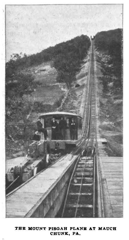
The oldest inclined plane in America, and probably the oldest in the world, engaged in the transportation of passengers, is the Mount Pisgah plane near Mauch Chunk in the Lehigh Valley, Pa. One of the peculiarities of this plane is that the ropes are not hitched to the passenger car, but to a special car or truck, known in the anthracite region by the name "barney." This truck acts as a pusher against the passenger car. It is on the lower side of the car, and thus, when the hoisting machinery is brought into action, the barney is pulled up and, in turn, pushes the car ahead. There is a peculiar arrangement on this barney that should be mentioned, namely, instead of two axles it has four half axles, each with a wheel mounted on it, and these axles are so attached to the truck frame that the wheels may be brought closer together and thereby the gauge reduced, or they may be spread for a wider gauge, as the situation may require.
From the illustration on the opposite page it will also be seen that the barney does not stand on the same track as the passenger car, but on a track located within a sloping trench, and that the track in the trench is considerably narrower than the track on the incline and also on the ground level upon which the passenger car stands. It will further be noticed that at the point where the slope begins there is a switch by means of which the wheels of the barney are adjusted to suit the gauge of one or the other of the tracks upon which it is to enter.
When the barney descends into the trench to a depth where it disappears below the ground level, the passenger car is free to move back from the inclined plane. The purpose of this arrangement is to avoid the necessity of permanently hitching the rope to the passenger car, because this latter is not only to travel on this plane, but to continue its journey on two other planes, all of which, combined with several gravity inclines, constitute a circuit by which the tourist travels over three inclines and three intervening slight down grades, starting with the ascent of the Mount Pisgah plane and finally returning to Mauch Chunk by way of a gravity plane from Mount Elias.
Considering the relative positions of the car and barney, as represented on the picture, they are just ready to start upon the ascent of the plane. The barney, on account of being still on the lower track, is not quite in touch with the rear bumper of the car, but will be so when both are on the same track.
Another feature of interest is the safety device employed for the prevention of accidents in case the hoisting rope should break. This device consists of a rack laid between the two tracks, extending over the whole length of the plane, and a pawl, automatically thrown into the rack by which the car is held fast upon the track in case the rope should give way.
The rope consists of a number of small strands of steel wires, which are laid parallel to one another and interlaced with wire, thus forming a ribbon. about seven inches wide. This is wound upon a wrought iron drum driven by a pair of 240 horse-power engines. The length of the Mount Pisgah plane is 2323 feet and the total rise is 664 feet. The plane is used mostly by tourists, and its passenger business therefore is confined principally to the warm season.

|
The second oldest inclined plane in America is the Monongahela passenger incline, located in Pittsburgh, Pa. This was opened to travel in 1870. It is 640 feet long and has a total rise of 375 feet, its grade being 71 1/2 per cent. The cars are each seven feet wide and fifteen feet long, divided into two compartments and a platform, surrounded with iron railings. The seating capacity of each car is thirty people and there is standing room for fifteen people, so that the total capacity is forty-five passengers. About 1,600,000 passengers are carried annually. The plane runs day and night.
The Monongahela Inclined Plane Company also operates a team incline alongside of the passenger incline. As to grades and length they are alike. The freight cars are each 17 feet wide by 32 feet in length. The hoisting capacity is about 20 tons. This plane has been operated since 1884. The cars each accommodate two heavy two-horse wagons or one four-horse wagon with the front horses turned sidewise. The running hours of the plane are from 7 A. M. to 7 P. M., during which time generally about 250 teams are transported.

|
The Penn incline, also in Pittsburgh, was built during the years 1882 and 1884 and was opened to travel on March 1 of the latter year. It was constructed with the view of hoisting 20-ton railway freight cars to the hill top. The purpose of this plane was the establishment of a coal yard on the hill top. Owing to the steep roads that lead to this section, coal was delivered there during the winter season at from one to two cents more per bushel above the price asked in the lower part of the city. As an empty freight car of 20 tons capacity weighs about 10 tons, the hoisting capacity of this incline was made equal to 30 tons against an empty car on the down grade, and with respect to this performance the whole of the incline was constructed. The incline cars are each 16 by 40 feet and weigh 30 tons when empty. There are two hoisting ropes of 2 1/4 inches diameter to each car, and a 2-inch safety rope is fastened to both cars. The aggregate ultimate strength of the two hoisting ropes for each car amounts to 300 tons when new, and about half as much when thrown out of service. Thus, their least aggregate capacity is about 150 tons, or about six times the greatest strain brought upon them.
The object in discarding the ropes while they still have a strength of six times the strain acting upon them is to provide an ample margin of safety in the case that one or two of these ropes should happen to break. This, however, has never occurred on an inclined plane in passenger service in these regions, on account of the close inspection exercised. The length of the track is 840 feet and the total rise, 335 feet. The main span of bridge work, reaching across the yard tracks of the Pennsylvania Railroad, is 232 feet. The plate-girder span next to the main span is 120 feet and the remaining spans are 60 and 40 feet, respectively.

|

|

|
|

|
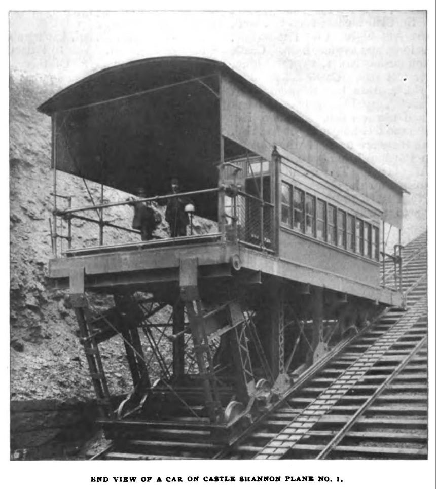
In addition to the Penn and Monongahela inclines there are in Pittsburgh the following :-- The Dusquesne incline, for passengers, 780 feet long, total rise 400 feet and a grade of 58.5 feet in 100 feet. The hoisting capactity is forty people. Mount Oliver incline, 1600 feet long, and 275 feet high. Knoxville incline, 2640 feet long, and 375 feet high. St. Clair incline, 2060 feet long, and 361 feet high. Fort Pitt incline, 350 feet long, and 135 feet high. Castle Shannon incline No. 1, 1375 feet long, and 451 feet rise. Castle Shannon incline No. 2, 2112 feet long, and 185 feet rise. Troy Hill incline, 370 feet long, and 160 feet rise. Nunnery Hill incline, 1100 feet long and 300 feet rise.

|
In all there are ten inclines in operation in Pittsburgh and two in its sister city Allegheny. The greatest single load hoisted up the Castle Shannon incline No. I was a 20-ton locomotive belonging to the narrow gauge railway connected with incline No. 2 and operated by the same company. The illustration on the opposite page represents the middle portion of the Knoxville incline, with both cars passing the curve which is the characteristic feature of this plane. In the background of this picture is seen the elevated ireon track construction of the Mount Oliver incline already referrred to. The Nunnery Hill incline was the first incline built with a curve. Its elevated structure is of wood and is soon to be replaced by steel construction.
|
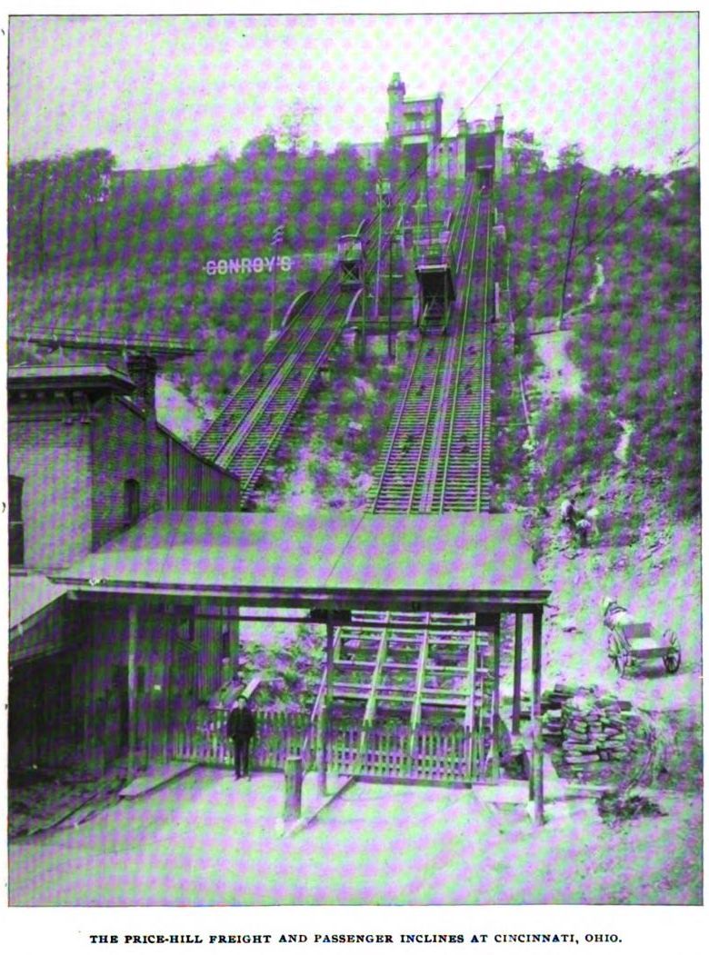
The city of Cincinnati, having six inclined planes, ranks next to Pittsburgh in regard to number. Of these, five are arranged for teams and passengers, and one is for passengers only. The Price Hill Incline Company owns and operates two inclines in the West End of the city, one carrying teams and the other passengers. Owing to the fact that these inclines run side by side, their general dimensions are alike, namely, length 800 feet, total rise 350 feet and grade 44.66 in one hundred feet.
The passenger incline has a capacity of sixty passengers. Its safety and hoisting ropes are both 1 1/4 inches in diameter. The capacity of the freight incline is 20 tones, and the safety and hoising rope are 1 3/8 inches in diameter. The general appearance of these inclines is shown in the illustration on page 93.
The safety devices of these inclines. are somewhat different from those of other inclines. There is a large sheave at the head of the incline and of a diameter equal to the distance between the centres of the two tracks. The safety rope, of which one end is hitched to each car, in the usual way, passes around this sheave. The journal bearings are so arranged that the sheave will slide forward bodily in case there should be any unusually heavy pull on the safety rope. By the forward motion. By the forward motion of the sheave its flanges are automatically pressed together by means of stationary jaws or wedges between which are the flanges. In this manner both the rope and the sheave are clamped and brought to a standstill.
The first incline in Cincinnati was operated by the Cincinnati Incline Plane Railway Company. It leads to Mount Auburn, a suburb of that city. It was first put in operation in 1872 when it was used for passengers only. It has since been remodeled and is now employed for passengers, electric cars, etc. The total length of this plane is 860 feet, with a grade of 30 feet in 100 for the first 250 feet, and 20 feet in 100 for the rest of the length. The safety and hoisting ropes are both 14 inches in diameter and the lifting capacity is 20 tons.
The other three inclined planes, operated by the Cincinnati Inclined Plane Railway Company, are all used for hoisting electric cars, teams and passengers. They are the Mount Adams, Belleview and Fairview inclines and are respectively 999, 1032 and 674 feet long, with total rises of 268, 300 and 210 feet, and average grades of 29.6, 32.25 and 35.15 feet in 100. The hoisting capacities, with the descending car empty, are 20, 15 and 10 tons. The maximum speed on all three is 700 feet per minute. Each of them employs two hoisting ropes per car, 1 1/4, 1 1/4 and 1 1/8 inches in diameter. The safety ropes are 1 1/2 inches in diameter throughout.
Among other American cities in which inclined planes have been built may be mentioned Duluth, Minn.; Johnstown, Pa., and Wheeling, W. Va. The Seventh avenue incline in Duluth was put in service in 1892. Its track work is 2975 feet long, all built on elevated steel structure. Its grades vary from 23 1/3 feet in 100 at the lower end to 15 feet in 100 at the upper end. There are two Corliss engines, directly connected with the drums, which are of the cable railway type. The plane extends from Superior street, the principal street in the city, to the hill-top north of the city. The total rise is 510 feet. The hoisting capacity is 25 tons, with an empty car coming down. The cars are 16 feet wide and 40 feet long and have, each, a passenger cabin 6 feet wide and 24 feet long. The greatest number of passengers hoisted at any one time was 407 on a day on which over fifteen thousand people availed themselves of the incline. The plane is owned and operated by the Duluth Street Railway Company of the same city.
|
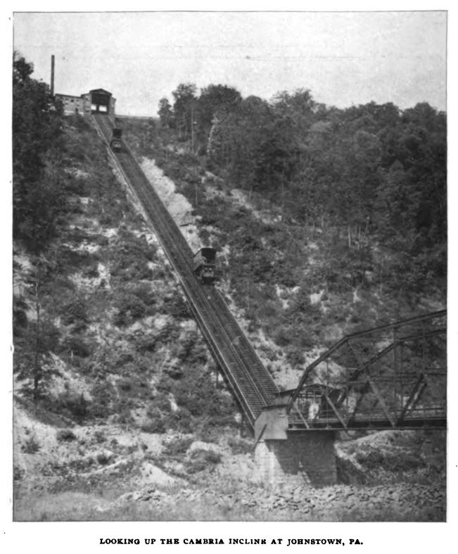
The Cambria incline at Johnstown, Pa., is another very interesting incline. It was projected after the great flood in June, 1889, and within thirty days after the occurrence of that disaster, steps were taken toward its construction. This was suggested by the low and rather damp location of that town, on account of which the cellars under the houses were frequently filled with water, seeping through the ground from beneath. The length of the plane is 895 feet, its total rise 581 feet and its grade is about 72 feet in 100. The view from the upper landing is one of the finest in the State of Pennsylvania. As seen in the illustration, on page 94, the lower end of the incline is approached by way of a bridge across Stony Creek, of about 300 feet span. This is reached by a wooden trestle structure rising gradually from the general level of the town. The cars are each 12 feet wide and 24 feet long. Owing to the steepness of the grade, the space under the read end of the car is so large that it afforded ample room for the insertion of a passenger cabin which is accessible by stairways at both stations. The platform is The platform is well guarded by strong wrought iron railings and stout booms that form a very strong barrier against the backing off of wagons in case the horses should become nervous.
|
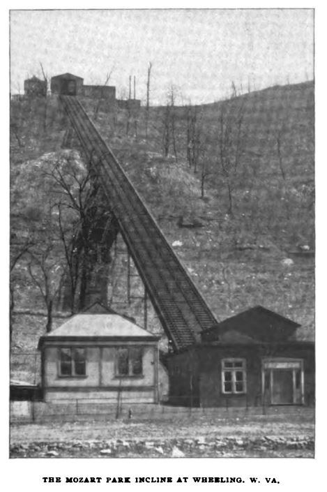
The Mozart Park incline in Wheeling, W. Va., was built for passenger travel only. The grade is 50 feet in 100, length 940 feet, and total rise 420 feet. It establishes communication between the city level and Mozart Park, which is situated on the hill. As there are no dwellings on the hill and the buildings there are solely for entertaining the people visiting the park, this plane is operated only during the warm season, when it is pleasant to be in the open air During the winter months it remains closed. The structure supporting the tracks is of steel and the whole plant is carried out in a very substantial manner. It was opened to travel in 1893 and is owned and operated by the Mozart Park Association, of Wheeling, W. Va.
The roadway of inclined planes consists, generally, of two tracks, with grades ranging from about 10 feet in 100 to almost a vertical ascent. AS a rule, two cars are employed and each of these travels forward and backward alternately, remaining, however, on its own track. The cars are hauled by steel wire ropes, set in motion by stationary winding machinery, located, in most instances, at the upper terminus of the incline. The connections between cars and ropes are permanent, and the cars are so constructed that their floors are in a horizontal position throughout the whole trip. In cases where the grade of the track is not uniform, but variable, the cars are designed to suit an average of the extreme grades. The rails are generally 60-pound T rails of ordinary sections. The gauges vary from 40 inches to 10 feet, the latter being adopted on nearly all of the team inclines in Pittsburgh.
As mentioned before, the hoisting plant is located at the upper end of the plane, where also any special safety appliances for the purpose of greater security are situated. At the foot of the plane the tracks extend into a pit in which the cars recede until their floors are brought level with the floor of the station. Likewise, the floor of the car at the upper end is brought to the elevation of the landing floor. The ropes are so adjusted that the cars arrive simultaneously at their respective landings.
The control over the operation of the machinery is exercised by an engineer stationed in the cabin at the head of the incline, and so situated that he has a full view of the cars as far as local conditions permit. Of brakes there are various kinds, -- steam, air, foot, hand, and gravity brakes, and there are always two, and sometimes three, installed within easy reach of the engineer. The foot brakes are used principally for checking the speed, but not for the entire stoppage of motion, for which end powerful mechanical brakes are required. Among the best adapted for this purpose are the Westinghouse air brakes, which are now in use at Pittsburgh, Johnstown, Pa.; Wheeling, W. Va., and Duluth, Minn. They are very reliable and so effective as to stall the machinery when running under full team.
On several inclines an auxiliary throttle and a Westinghouse air brake are so arranged that they will automatically act in case a car should come closer to the edge of the upper landing than is desirable. In this event the throttle shuts off the steam from the engines and simultaneously the air brake comes into action, which results in bringing the machinery to a quick standstill. The principal object aimed at in the employment of this combination of throttle and air brake is to provide against the consequences that would follow the sudden inability of the engineer to perform his duty from any cause.
There is another air brake which is applied by the engineer at each run when the cars come to a stop. It is brought into action by a valve located at the reversing lever and the main throttle lever. On some of the freight inclines, as the Penn and the Monongahela, the reversing of the links is performed by a special small engine, because, owing to the large area of the slide valve, the friction under steam is too great to be overcome by a man's unaided exertion. At the Cambria incline, at Johnstown, the reversing apparatus is operated by compressed air instead of steam.
Steam brakes were found very unsatisfactory on inclines and were therefore discarded where formerly used. The trouble with them is that they are used only after intervals of from five to thirty minutes and for this reason are cold when wanted. On this account no effect is derived from the first steam as it enters the brake cylinder, because it condenses and fills the latter partly with water until the cylinder is warmed up. Owing to this circumstance steam brakes do not act with the promptness that the service demands.
The engines employed on inclined planes are of the ordinary type, mostly of the slide valve type, preferably balanced; they are always in pairs, coupled, and with Stephenson links. In several instances automatic engines were adopted, but these, as well as compound engines in one case, do not produce any material saving in fuel, but, on the other hand, are rather a detriment to the maintenance of the plant, because every additional complication of the machinery increases its liability to derangements. As inclines in passenger service are required to run at all hours during day and night, the simpler the power plant is, the more can it be relied upon. This is a matter of vital importance because there is no time during which extensive repairs can be made.
The starting of the cars is governed by a code of electric gong signals between the conductor at the lower end of the inclined plane and the engineer in the cabin. There are three signals. The first announces that the conductor below is getting his car ready to start. This is answered in acknowledgment by the engineer. Then follows the second signal by the conductor, which means that the car at the foot of the plane is ready to start. This, too, is answered by the engineer, and immediately thereafter the engineer gives the third signal, which means that the cars will start. Owing to the close inspection of every detail whose derangement may become detrimental to the operation of the plane, and the perfect understanding between the engineer and the conductor at opposite ends of the incline, accidents on passenger inclines have been rare occurrences.
The safety apparatus by which the safety rope is controlled, consists of two sheaves, each having three grooves and a broad brake rim for the accommodation of a steel band. These sheaves are arranged in a manner similar to the drums used in cable railway machinery, except that in the latter case the machinery or drums drive the rope, whereas in the safety device of an inclined plane the sheaves are driven by the rope which, in turn, is moved by the cars.
In both kinds of service the efficiency depends upon the friction produced between the rope and the grooves. This is attained by throwing several coils around the sheaves. If, by so doing, enough friction is produced to prevent the rope from slipping in case the hoisting ropes should break and the overweight between the two cars be thrown on the safety rope, it remains only to provide such a breaking device as will prevent the safety sheaves from revolving. This end is accomplished without difficulty by the use of steel bands, put around the brake rims already mentioned, and by means of a proper combination of levers, or chains, shaft and hand wheel. This latter being erected in the cabin, the engineer is in a position to prevent an accident in case the hoisting rope should fail.
This type of safety apparatus has been generally adopted on all inclines built since 1875. since 1875. Prior to that time only a single sheave, equal in diameter to the distance between the centres of the two tracks, was employed. The efficiency of this device was not very great, because the friction produced between the rope and the sheave, extending only over half a circle, was too small to be very effective in case of a break in the hoisting rope. With a break occurring on the side of a heavily loaded car, the latter would go down the hill notwithstanding the application of the surface brake, for this would not hinder the rope from slipping, though the sheave might be held stationary. Fortunately it must be said to the credit of the superintendents of inclined planes, that ropes are never kept in service until their strength becomes doubtful, but are removed before their deterioration becomes 50 per cent. of their original strength.
The safety devices on the inclined planes in Cincinnati are the same as on most other modern inclines, but they have, in addition, a special device, the function of which is to hold the car against the upper landing in case, by a forcible collision with that landing, the hoisting ropes should be torn off in some manner. This device is known as Rancevau's patent safety hook. In construction and operation it resembles an automatic car coupling. It is so located on the track at the upper terminus that when a car comes to its landing, the hook automatically hitches to the truck frame and remains in this condition until the engineer moves the reversing lever to set the links for the next run. long as that lever stands on the middle notch of the quadrant, the hook remains engaged to the truck, and only by throwing the reversing lever into one. or the other extreme position will the car be released from that hold.
Concerning cars, there are several types in use; first, among passenger cars, the ordinary street railway car on an inclined truck; second, for steep grades, as for that on the Monongahela passenger incline, a car, divided into several compartments, entered sidewise, and each one higher than the preceding one. Among the cars for heavy service are, first, the plain car, consisting of frame work, wheels and axles, and a strong floor, guarded by stout railings on the long sides, and booms, and swinging or folding gates at the ends; second, the same car with a narrow and long passenger cabin on one side; third, on steep grades, like that of the Cambria incline, floor, railings, and other details the same as in the first case, but a passenger cabin under the main floor; and finally, a car like that first described, but with passenger accommodation on a second floor, that is on the roof over the main floor. This latter type was in use on the St. Clair incline in Pittsburgh, but for a short time only; it proved to be entirely too shaky to be pleasing to the passengers.
The frame-work of the cars is now made entirely of steel because wood is not strong enough to withstand the constant vibration under heavy strains without getting loose in the joints. Most of the heavy service cars in Pittsburgh are provided with air bumpers, similar in construction to the well known Westinghouse air-brake cylinders, but larger in bore and stroke. Experience proved that they are more effective and more reliable and of much wider range of action than bumpers made of springs. They possess the further valuable advantage of being capable of exact adjustment to the demand of the service.
There are generally two members in the truck construction to which ropes may be hitched, and it is a rule to hitch the hoisting ropes and the safety rope to different beams, so that in case one hitching beam should be destroyed, there is another one to be depended upon. These beams. when correctly dimensioned, are of such strength that the ultimate strain of the ropes is not enough to affect them in any manner whatever.
Provisions are also made to prevent teams and cars from rolling off the car floor. Several methods are employed to accomplish this end. In some cases heavy gas-pipe booms are thrown across the ends of the floor and simultaneously heavy timbers rise from the floor to a height of about twelve or fifteen inches, and are firmly held in that position until the conductor raises the boom by which operation the guard timbers are made to sink into corresponding spaces in the floor. This device is adopted on the cars of the Penn incline and the Castle Shannon incline No. 1. On other inclines wooden booms are used, and the wheels of cars are blocked and those of ordinary vehicles are chained to the floor. Again on some, swinging gates or folding gates are used. The weights of cars used for heavy service vary from fifteen to thirty tons.
Go to top of page.