This article, from The Street Railway Journal, August, 1889, describes the first powerhouse of the Chicago City Railway, the first cable traction operator in that city. Note that the Hazelton Tripod Boiler produced superheated steam.

|
The original cable-driving plant of the Chicago City Railway Co.
located at the corner of State and Twenty-first Streets has deservedly
won the admiration of many thousands of Chicago's citizens, as well as
of numerous visitors from all parts of the world, by whom the powerful
machinery which it contains has been inspected.
In spite of the fact that this station having been built in '81 and '82,
is one of the earlier enterprises of its kind in this country and that
meantime the builders much of its machinery have naturally improved
their designs, as may be seen in the more recently established plants of
this company, the Cottage Grove Avenue plant for example -- its
arrangement so perfect, its machinery so powerful and effective in the
performance of its work, and its operation so continuous and generally
satisfactory, that it may safely be termed a model power-house; and the
object in view in the present article is therefore to present to our
readers a general description of it, together with particulars of some
of the more prominent features To begin with, then, our next page
illustration presents a ground plan of the entire establishment, showing
the location of the boilers and machinery, with the tension carriages,
the cables and their appurtenances. A study of this plan will show the
admirable arrangement which prevails, and it will be seen that under the
same roof are the company's general offices, which with the engine
rooms, car house and car factory occupy a full half block, a space
equivalent to two and a half acres or more. Here the various officials
of the company have their offices, the number of the office entrance,
2020 State Street, being undoubtedly familiar to many street railway
men. The arrangement is such that no time is lost in passing from one
department to another, nor is any space wasted, and the impress of the
same master mind is to be seen here as well as in the plan of the power
nouse. All the departments comprise much in little, or, in other words,
the most is made of every part; and each engine, drum, sheave and pulley
is fixed in the place most appropriate for it.

|
The first pair of engines stand at the southeast corner of the power-house (and of the building); between them are a ponderous fly wheel and a set of main shaft gearing. Next thereto, to the northward and parallel, is a pair of drums over which the No. 1 cable that (operating the upper part of State Street) passes. Then comes the first set of drum gearing; and on the other side is the set of drums over which passes the Wabash Avenue cable (No. 3). For the information of those who may not be familiar with the vicinity, it may be well to say that State Street is a long and straight thoroughfare (one of the busiest in the city), running north and south. Wabash Avenue is more of a residence street and runs parallel with State, one block apart. The cable for Wabash Avenue passes along State Street, one block south to Twenty-second Street, and thence through a tunnel to Wabash Avenue. Both these cables reach to Madison Street and back, that on Wabash Avenue being about three blocks the longer (including the distance from the power-house to where it begins to propel the cars). The distance from Twenty-first to Madison is about two miles, and hence these cables are each more than four miles long. Then from Madison to Lake Street (two blocks further north) a loop cable (No. 5) takes the Wabash Avenue cars to Lake Street, to State Street, to Madison Street, and back to Wabash Avenue. This loop line is driven by the Wabash Avenue cable. Another loop line (cable No. 6), connected with the State Street cable, takes the State Street cars along Madison Street to Wabash Avenue, along the latter to Lake Street and along Lake back to State Street; thence forward to the main (No. 1) cable. Both of the loop ropes run in the same tunnel, or tube and it was here that at the beginning some difficulty was experienced until the gripmen became masters of their work.
The speed of these main cables which operate in the very heart of the city is eight and a half miles per hour, while cables Nos, 2 and 4 move at a speed of nine and a half miles an hour and those of the extensions beyond Thirty ninth Street run at the rate of twelve miles an hour. The loop ropes, it should be stated, move at half the speed of the main cables.
The half of the power-house already described is separated from the rest by a passage-way from the front to the back part of the premises. On the other side of the passage-way is the pair of drums belonging to cable No. 4. Next is the second set of drum gearing and on the other side thereof are the drums of No. 2 cable. Cable No. 4 operates the Cottage Grove Avenue road as far as Thirty-ninth Street which avenue starts at Twenty-second Street two blocks east of Wabash Avenue and runs in a southeasternly direction to Thirty-ninth Street the distance being about two and a half miles (five miles of rope) from the power-house Cable No. 2 operates the cars on State Street from Twenty-first to Thirty-ninth Street a distance of about two miles; and No 4. operates the Twenty-Second Street loop designated (No. 7 cable).
These four cables with the three loop lines make a total of twenty and a quarter miles of rope They were built between seven and eight years ago, the first (State Street) being opened January 28, 1882 At that time there was no occasion to run cars beyond Thirty-ninth Street (the old city limits), and the two original engines afforded sufficient power for the traffic of those years. But the cable lines soon attracted inhabitants beyond their termini and in 1886 and 1887 they were extended on State Street to Sixty-third Street (adding three miles of road), and on Cottage Grove Avenue to Sixty-seventh Street with a branch road eastward on Fifty-fifth Street (an extension of nearly four and a half miles of road), making a total of thirty-five miles of cable. These extensions, however, are operated from separate power houses but as they connect with the original cable roads they add immensely to the number of passengers thereon, which now one million per week. Over one hundred miles of horse car tracks also feed the main uptown cable lines and over the whole of this South Side system a passenger can proceed (if in one continuous journey) for a single fare of five cents. Thousands avail themselves morning and evening of the facilities thus furnished, some seven miles, some ten, some twenty, and this travel is so regular that Mr. Holmes the president and superintendent knows almost exactly how many transfer tickets will be required each day.
The ropes used on these lines (we are indebted to the "Souvenir," a handsome little descriptive volume by H. H. Windsor, secretary of the company, for some of the data and illustrations given herewith) are an inch and a quarter in diameter containing six strands of sixteen wires each with large wires on the outside twisted around a central strand of hemp. The cables are tarred and oiled as they enter the power station and their entire length carefully inspected every night while moving at four miles an hour, and of course after the day's work is finished. The average life of a cable is about 40,000 miles but lately, some ropes have run much greater distances, two of those run from the State Street plant being recently still in service and in good condition, the one with 60,000 miles to its credit and the other 58,000. On Cottage Grove Avenue there are records it is said of 69,300 and 83,900, at a speed of twelve miles per hour running twenty hours daily and on the State Street line of 106,000 miles. Other records are reported of 95,000, 76,800 and 97,400 miles on the more recently constructed lines.
The absence of curves and the use of a long grip, coupled of course with excellence of material, is accountable for the long service of the cables. The serious effect of curves and especially of reversed curves is recognized by all cable road superintendents. It shows in the rapid wear of cables and excessive consumption of fuel for motive power. The advantages of a long grip over a short one are that less pressure is necessary to move the car, consequently there is less danger of stranding and of hardening the cables by friction It also overcomes the rocking motion of the car to a certain extent When the grip has the cable fast the rocking motion breaks the wires at each end of the grip just as they would be broken if bent backward and forward by hand When the fact is considered that this rocking bends the cable hundreds of thousands of times every day it is not strange that short grips make short life for cables.
But to return to our subject. One pair of engines managed to drive the four main (original) cables with their auxiliaries until about eighteen months ago when two more engines were added. It is remarkable that the necessity for two extra engines had been foreseen when the plan of the engine house was arranged and space reserved for them. The new engines with their great fly-wheel and shaft gearing, are placed on the north side of the four pairs of cable drums and their gearing but further back and partly alongside the place of the tension carriages which are just in the rear of the cable drums. The gears and shafts are so arranged that the whole four engines may work together, or one pair of engines may (as is the usual rule) drive two of the cables those going to the northward (Nos. 1 and 3) being operated by the first pair of engines and those going to Thirty-ninth Street (Nos. 4 and 2) by the new engines. A boiler capacity of 1,000 H. P. was originally provided at this station, four 250 H.P. boilers of the Babcock & Wilcox water tube type having been erected; and it is said that the excellent performance of these boilers under the severe service demanded of them has fully demonstrated their good qualities as and economical steam generators. Somewhat recently these boilers have been equipped with the Roney mechanical stoker and smokeless furnace, a description of which is given later on. When the immense increase in travel on the original cable lines demonstrated the necessity of extending them and the power station at State and second Streets was accordingly established, a plant of three 350 HP Hazelton tripod boilers was adopted. This is a boiler of an entirely different type, the merits of which the company had been meanwhile investigating and as they considered that in some respects the Hazelton boilers were preferable for the requirements of these power plants they were adopted when the magnificent new station at Cottage Grove Avenue and Fifty-fifth Street was built, three of them, having a capacity of 600 H.P. each (said to be the largest single boiler in the world), being installed, while later in the same season when increased boiler capacity at the original State Street plant was found necessary, two 500 H.P. Hazelton were added to the original Babcock & Wilcox plant as may be seen by reference the plan. Each of these boilers is equipped with three mechanical stokers.
The four engines are capable of developing 3,000 H.P., but the usual force is only about 1,200. About two-thirds of the power developed is used in propelling the cars, the remaining third being required to move the cable. The ordinary number of cable cars operated at one time is about 400, and they keep on running more or less of them for twenty-one and a half hours out of every twenty-four, the cable having a rest ceases running from 2.20 to 5.00 A.M in Summer while, in Winter its "sleeping time" is not more than forty minutes, and sometimes when the frost threatens mischief and the pulleys and sheaves are liable to freeze if not kept running, not over ten minutes.
In front of the new pair of engines there has been placed recently one of Ide's "Ideal" engines to drive a couple of electric motors, one a Thomson-Houston incandescent light motor, the other an "Excelsior" arc light motor. The power-house is lighted by both lights, the incandescent only being used in the offices The engine is 60 H.P. and will make 270 revolutions per minute The "Ideal" is drawn from the inventor's name A. L. Ide by affixing the initials to the surname.
A word about the horizontal sheaves just outside the house and underneath the roadway is necessary in a description of this model cable plant. A pair of twelve foot horizontal sheaves guide each cable in and out of the power house Cable No 4. (Cottage Grove Avenue) passes over the pair of sheaves nearest the building. No. 3 cable (Wabash Avenue) passes over the next pair. No. 1 cable (State Street to Madison Street) passes over the other pair of sheaves in line with the pairs already mentioned; and cable No. 2 (State Street to Thirty-ninth Street) over the pair of sheaves to the north of the latter. The average life of a rope is twelve months. Some last longer while some do not last so long. The least sign of weakness is enough to condemn a rope. Mr. Holmes does not wait for a breakage.

|
Fig. 1, showing a sectional elevation of a 350 H.P. boiler with two Roney stokers attached will enable those interested to better understand the construction and setting of a Hazelton boiler which differs radically from the ordinary type of boiler. It is claimed for them that they possess a number of important advantages and are not only the safest but the most economical of steam generators as the entire boiler is heating surface and the full force of the heat is applied most effectually.
Their distinctive features consist in an upright centre column, the sediment falling by gravity to the bottom, where it is easily removed and the radial arms are short, being twenty-four to thirty-six inches in length and affording a very rapid circulation. These arms are made of regular boiler tubes with one end closed and the other expanded in a hole bored in the centre column. There is no pull or strain on the joints as the tubes are made fast at one end only and can expand freely as heat is applied. Large domes are provided at the water line which increase the water area, and steam is given off free of water. The part of the boiler above the water line is steam space and the tubes above the water line act as steam dryers. Thus with this boiler the steam is hotter than the temperature due to the pressure as it passes in all the tubes above the water line before it leaves the boiler. The gain from this alone it is said is great as the steam is dryer and hotter enabling the engines to cut off shorter on account of the greater expansion of dry steam. All the parts of this boiler are easily accessible for repairs and cleaning. A very desirable feature is that the ground space required is comparatively very small, a 500 H.P. boiler only seventeen feet. No stack is necessary as the bricking in of this boiler forms the stack.
The foregoing account of the boilers at this steam plant would be incomplete without a description of the stokers and furnaces with which these plants are equipped and which are to the boilers what the lungs are to the body, taking from the atmosphere the necessary oxygen to combine with the hydrogen and carbon of the fuel and producing a heat which sends the steam flying through the entire system of mains and pipes as the blood courses through the arteries and veins of the body.

|
The Roney mechanical stokers and smokeless furnaces are in use on all boilers of the City Railway Co., which fact is an evidence of how highly they are regarded by this company. To describe the operation of the stoker briefly, we would say the fuel is fed in from the hopper by a gradual motion, which can be regulated to feed little or much and the coal, as it enters is coked under the short arch at the front of the grate, and the gases given off in this coking operation receive the necessary air for perfect combustion from the hot air chamber with perforated bottom shown at the head of the grate and immediately over the coal as it enters the furnace. This air is heated in passing through the air spaces in the side walls, and mingling with the gases given off in the coking of the fuel produces practically perfect combustion so much so that the fire is smokeless when the supply of fuel is regular and constant. After the combustible portion has been burned the ash and cinder are deposited in the ash pit ready for removal This apparatus may be seen in Fig. 1, as attached to a Hazelton boiler and in Fig. 2, a general section on a large scale is shown The fuel to be burned is dumped into the hopper on the boiler front In small plants it may be shoveled in by hand In large plants such as in the State Street power house, Fig. 3, it is usually handled direct from the car to the hoppers by elevators and conveyers.
The grate bars which extend laterally across the furnace are constantly in motion and form alternately a series of steps as shown in the cut and then by a forward rocking motion dip down until they overlap like shingles on a roof, forming a favorable surface for the forward movement of the coal, but before it slides too far the grates return to the stepped position, thus checking the downward motion of the coal and breaking up the clinker thoroughly over the whole surface of the grate and admitting additional air for the combustion of the fuel. This alternate sliding and checking motion being constant, finally lands the cinder and ash on the lower dumping grate, when by releasing the handles shown in the cut the grate tilts forward, throwing the cinders into the ash pit, when it can again be closed, ready for further operation.
From this brief description it will be seen that the stoker can be operated continuously, and the fire can be forced whenever and as rapidly as desired, without opening doors for the supply of fuel or cleaning grate. This is an important feature in its construction and an element of the economy in the operation of the stoker. For, as is well known, the continual opening and closing of doors in the ordinary method of firing is not only a source of loss in fuel but a severe strain upon the boiler shell on account of the unequal contraction and expansion it causes. In mechanical stoking the furnace is never open to the outside air, hence its temperature is always high and always uniform, a most important consideration often overlooked. The effect of this on the life and of the boiler is evident.

|
It is hard to conceive of a simpler device for accomplishing so important a purpose. The stoker is strong and well built, having in view the conditions of its operation and the usual nature of its attendance. There are few pin connections or finished parts. The strains are exceedingly light and the motion is so slow as not to be perceptible to the casual observer. Any single bar can be picked out and replaced even easier than in the ordinary flat grate. On account of the free circulation of air through the grate, due to the constant rocking motion, the bars are kept cool and consequently are long lived The boiler fronts are plainly but handsomely modeled in accordance with the prevailing idea of mechanical contour. The application of the stoker to the remodeling of existing boiler plants is fortunately easy. The stoker itself is independent of the masonry of the boiler setting. In setting a stoker the lower half of the boiler front is removed. The stoker is then erected in place without other disturbance of the boiler setting. The stoker is manufactured and sold throughout the Unived States by Messrs. Westinghouse, Church, Kerr & Co., New York, Chicago, Boston and Pittsburg; Chicago office, 156 & 158 Lake Street.
|
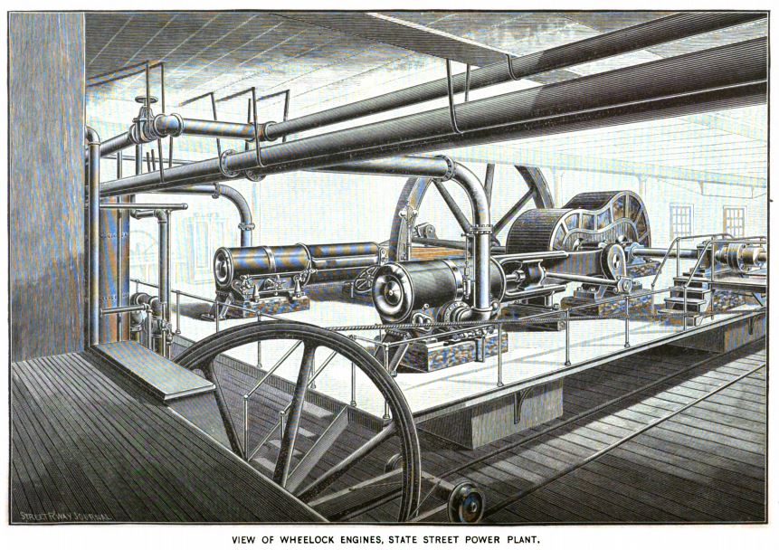
The engines which drive the cable winding machinery of this extensive plant are known as the "Improved Wheelock" engines from the Wheelock Engine Co., of Worcester, Mass. The general appearance may be seen by reference to the engraving on the previous page, which presents an interior view of the State Street power house. The most remarkable feature of this type of engine is the valve system, the exterior parts of which are shown in the engraving. The valve employed is a multi-ported slide working on a flat seat formed within a skeleton plug or shell, through which passages are cored forming ports into and out of the cylinder The valve and operating parts being mounted upon or within this shell, they together form a complete and self contained piece of mechanism entirely independent of the cylinder. The shell is turned slightly, tapering to fill corresponding holes in the walls of the steam chest, and being ground to a steam-tight fit therein, it, with the contained valve, seat and operating parts, is lightly driven into place and is retained secure without the need of other means of fastening than results from the tapered driven fit.
The valve is operated from a rocking spindle having bearings in the ends of the shell. Motion is communicated from the spindle through crank arms and a pair of short links connecting the latter with the valve and forming a toggle joint which converts the rotary motion of spindle into reciprocatory motion of valve. The spindle works in hardened steel bushings and is itself of steel hardened and ground as are also all the running parts of the valve. The spindles are self-packing by the action of steam pressure forcing the accurately ground face of a collar against a corresponding face of the end of the bushing. Upon the outer end of spindles are keyed cranks, driven direct from the eccentric in case of the exhaust valves, those of the admission valves being operated from the others by latch links which alternately hook on and let go through the action of a curved finger engaging with trip-cams adjusted by the governor, thus accomplishing cut-off in an obvious manner.
It is apparent that when the strain on the engine varies so suddenly and violently as on a great cable road, where it may happen that a large number of trains have to be started at the same time, or may be all as suddenly freed from the cable during stops, a quick-acting automatic cut off engine which shall instantly reciprocate to the varying strains is an imperative necessity, and from adoption by the Chicago City Railway it would that the "Improved Wheelock" filled all requirements. The dimensions of the two pairs in use in the plant under description are 30" X 60" extra heavy throughout, and capable of developing a total of 2,200 H.P. The other (all Wheelock) in use by the same company are: One pair 36' x 72' = 2,000 H.P.; two pairs 24" X 48" = 1,200 H.P.; one 16" X 48" = 125 H.P.; making a total of 3,325 or in all of 5,525 H.P. These are said to be low ratings, however, the nominal rating being 6,000 H.P.
|
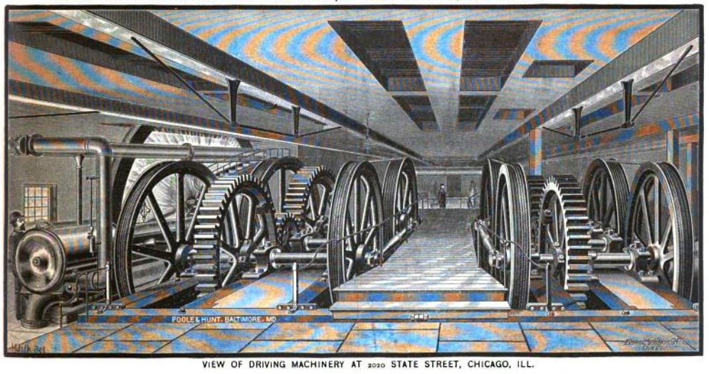
The driving machinery for all the cables of the Chicago City Railway Co. came from the well known firm Poole & Hunt of Baltimore, Md., now Robert Poole & Son Co. Each pair of the engines above described has a shaft, eighteen inches diameter, which with the crank weighs about 20,000 lbs. The main driving pinions fastened to the crank shaft are six feet diameter and thirty-two inches face, weighing 20,000 lbs. each. The teeth are of double helical type and mesh into those of the main driving gears (ten feet diameter), fastened to the main line shafts. These gears weigh 28,000 lbs. each and are cast in one piece. They are marvels of the moulder's skill, running true and, considering the great power transmitted, comparatively noiseless, although there has been no machine work done on the teeth, they being left just as came from the sand. The fly-wheels on the engine crank shafts are twenty-four feet in diameter, and each weighs 90,000 lbs. Each of these monster wheels is made in sections, so accurately fitted and bolted together, that although the outer rim travels at the rate of a mile a minute, there is no perceptible variation from its true and even motion. The main line shaft is fifteen inches diameter and sixty-eight feet long. It is in four sections and revolves in eight bearings. There are two pinions on line shaft, one five and one six feet diameter, sixteen inches face, weighing respectively 8,000 and 9,000 lbs.
Meshing with each driving pinion is a ten-foot diameter gear weighing 14,000 lbs. Said gear is fastened to a shaft, carrying a drum on each end. A second pair of drums is carried by a shaft having a similar gear while between the two there is an idler shaft, with a five-foot diameter pinion. The drums driven by the six foot pinion on the main line shaft drive their cables one mile per hour faster those driven by the five foot pinion. The drum shafts are ten inches diameter and sixteen feet long, and run in blocks sixteen inches long, which are bolted to a heavy cast iron framework, which in turn is anchored to solid concrete foundations, thirteen feet deep. Usually the bearings for drum shafts are placed on either side the drums, but here the drums are hung outside the bearings and the outer ends of each pair of drum shafts are connected by a strut, which can be adjusted for wear and which relieves the pillow blocks of the strain caused by the cable passing around the drums. The drums being outside their bearings permit the ready removal or replacement of the cable if desired and allows making an extra lap when the cable has stretched to such an extent that it would otherwise be necessary to cut a piece out. The drums are twelve feet diameter, weighing 12,000 lbs. each and have six one and a quarter inch turned grooves in each.
The incoming cable passes around its pair of drums with two or three wraps as the case may require; their leads from the bottom of the drum to the tension carriage, where it passes around the tension wheel from the under side, and leads out into the street, passing around a twelve-foot horizontal sheave, and is afterwards elevated to its proper level in the channel. The drums, gears, engines and shafting make an aggregate weight of over one million pounds and occupy a space 151 ft. long and sixty feet wide.
In all this heavy machinery the utmost nicety of struction and finish prevails, and great pains were taken in the casting of these immense drums and wheels, in the selection of the iron and in having the molten metal in just the proper condition when the castings were poured. One little defect in a single tooth of the hundreds so rapidly turning in this multitude of wheels, might cause wreck and ruin to them all.
A few words in passing with regard to the tension carriage, a simple but most essential requisite of a cable road. The cables, in order to receive any motion, must be always taut on the drums. To secure this automatically yet effectively, the cable as it comes into the power station is passed around the drums and thence before returning to street around a vertical iron sheave weighing 3,000 lbs., twelve feet in diameter, with a one and a quarter inch groove in its rim. This wheel is set in a wrought iron frame, twelve feet long, carried by four flange wheels on an ordinary steel T-rail track with a forty-four inch gauge. At the farther end of this carriage is attached a heavy chain, which may be shortened or let out at will by means of a sprocket wheel. This chain passes over a pulley and suspends in a pit a weight of 4,000 lbs As the moving cable comes in taut or slack the carriage moves forward or backward, and the weight in the pit rises or falls. The great weight of the cable causes a sag of one and a half inches between each carrying pulley When a heavily loaded train grasps the cable in starting this slack is all taken up for some distance ahead but in a few seconds when the train has secured its momentum, this slack is replaced. Were it not for the mobility of the tension carriage this sudden and constant tightening and loosening of the cable by the multitude of trains would prevent a steady and uniform motion of the cars The tension also takes up the natural stretch, which in a new rope five miles long amounts to fifty feet the first day, and often as high as one hundred feet the first week, after which the stretch is nominal.
Go to top of page.