These articles from Manufacturer and Builder Magazine were published in the late 1880s, the high point of the cable railway era. Photo scans of the articles are available from Making of America at Cornell University. Uncorrected text scans are available from the Library of Congress' American Memory site. I did some cleanup of the text scans. I made a few editorial comments in italics with my initials.
- Notes and Queries (March, 1885)
- Notes and Queries (July, 1888)
- A Combined Gravity and Cable System for the Operation of Elevated Railways in Cities (October, 1888)
- The Heckert System of Cable Railroads (December, 1888)
- The Sprague Electric Railway System (December, 1888)
- An Improved Gripping Device and Accessories for operating Cable Railways (May, 1889)
- Notes and Queries (May, 1889)
- Running Locomotives with Soda Instead of Coal (June, 1889)
- The Traffic of the Cable Railway on the New York and Brooklyn Bridge (November, 1889)
- Excerpt from The Pneumatic Rolling-Sphere Carrier Delusion (December, 1889)
- Selected Articles From Manufacturer and Builder (1870-1879)/Page 1
- Selected Articles From Manufacturer and Builder (1870-1879)/Page 2
- Selected Articles From Manufacturer and Builder (1880-1884)
- Selected Articles From Manufacturer and Builder (1885-1889)/Page 2
- Selected Articles From Manufacturer and Builder (1890-1899)/Page 1
- Selected Articles From Manufacturer and Builder (1890-1899)/Page 2
Notes and Queries
From Manufacturer and Builder /Volume 17, Issue 3, March 1885
This item explains how cable cars lines cross each other. It describes a top grip system, like the one in Philadelphia.Q. 3546. CABLE RAILWAYS -- I have been at a loss to understand how one line of cable railway can cross another at intersections. How is it done in practice ? -- H. C., Philadelphia.
Answer. We have not had the opportunity of observing or learning what the practice is in this particular in Chicago and other cities where the cable system is in use, but can state what plan will be adopted in Philadelphia, where, in a few months, an extensive system of cable railway will be in operation. It is as follows: Two guide pulleys (in which the cable rests) of one of the lines that intersect, are supported at a somewhat higher level on the two sides of the intersection, and between them is placed another guide pulley (at the center of intersection), supported in the base of the trench, much lower than the usual level of the pulleys. The cable of one of the lines thus provided, on reaching the intersection, is first slightly lifted above its normal level (To lift the cable out of the top grip - JT) in the trench by passing over the first elevated pulley, then depressed considerably below this level by passing under the depressed pulley, then raised again above by passing over the second raised pulley. A section of the cable at this point would have a V shape, and the cable of the other intersecting line would be seen in the center of the V. The gripman, in crossing the intersection, supposing him to be on the line with the depressed cable, would, on approaching the intersection, release his grip, and allow his car to cross the other line by its own momentum.
Go to top of page.
Notes and Queries
From Manufacturer and Builder /Volume 20, Issue 7, July 1888
This brief item describes the history of street railways.Q. 4077. STREET RAILWAYS. -- Noticing your very circumstantial answer to an inquiry about rails in the last number of your journal, I venture to ask you the following questions: When were street railroads introduced in this country? Why are they called tramways in England? How long has the cable traction system been in use? and where did it originate? Your answer will be much appreciated. -- H. G., New York.
Answer. Street railways, for the conveyance of passengers, appear to be an American invention, and were introduced in this country, in an experimental way, about the year 1810 (? - JT). It was not, however, until several years later (about 1815) that their adoption became general. In New England, in fact, the first horse railway -- that between Boston and Cambridge -- was not introduced until the year 1858. In reference to the origin of the term tramway, there is some difference of statement among authorities. Knight, in his "Mechanical Dictionary", defines a tram to be: 1. "A four-wheeled truck for carrying a corve, hutch or basket on a pair of rails in a mine, or in carrying coal or ore. 2. One of the rails of a tram-road." Raymond, in his glossary of mining terms, gives a similar definition, namely: "Tram" (Wales), 1. A four-wheeled truck to carry a tub, corve or hutch; or to carry coal or ore on a railroad. 2. One of the rails of a tram-road or railroad." The tramway would, therefore, be the stone, wooden or iron way which served as the track for the wheels of the trains or coal wagons. They were the precursors of the iron railway. Tramways were in use in the English and Welsh collieries for more than two centuries. Tomlinson, in his encyclopedia, would make it appear that the term tramway is of comparatively recent origin. He states that the word "tramway" is derived from the name of Mr. Outram, a gentleman extensively connected with the collieries in Newcastle, England, these roads having at first been called "outramways" (or outram roads). This derivation, however, does not appear to be supported by the facts, and the similarity between tram and Outram is probably an accidental one. This is rendered almost certain by the term being very ancient, since it appears also in the old German. Flagstone tramroads were laid down on certain business streets in London in the early part of this century, to facilitate the heavy traffic of the East and West India docks. When street railways were introduced in England (in 1818), their similarity to the tramways just described, caused them to be called by the same name. Ure has the following allusion to the term: "An improvement . . . where men draw the coals, is to place the bucket or corve on a small four-wheeled carriage, called a 'tram'. . . . The transport of coals from the wall-face to the bottom of the shaft was greatly facilitated by the introduction of cast-iron rails in place of wooden roads. . . . The rails are called 'tram rails.'" The cable-traction system for city railways (also an American invention) was first introduced, in 1878 (1873 - JT), in San Francisco.
Go to top of page.
A Combined Gravity and Cable System for the Operation of Elevated Railways in Cities
From Manufacturer and Builder / Volume 20, Issue 10, October 1888
April Fool's? Apparently not. L A Thompson (no relation) was a pioneer designer and builder of roller coasters. Here he proposes using the same techniques to operate an elevated railway. It would have been a fun ride if it had been built.

|
Thompson's Gravity System for Rapid Transit in Towns and Cities (270k image). |
The question of providing means for rapid transit in large cities is properly regarded, in all progressive communities, as having a most important bearing upon their growth and development. As the final solution of this problem, two systems have come to be recognized -- the elevated and the underground. The last-named has received its greatest development in London; the first, in New York. It is with the elevated system that we shall concern ourselves here, since this has received a thorough trial in the metropolis of our country, and may be regarded as the typical American system of rapid transit in cities.
It would be gross exaggeration to affirm that it has proved an unqualified success. It has answered its intended purpose of effecting the rapid transfer of the population between the business quarter of the city and the upper parts of Manhattan Island, thereby greatly relieving the surface roads of overcrowding during the busy periods of the day, but at such a cost that it is gravely questioned whether, on the whole, the disadvantages of the system do not overbalance its acknowledged advantages. Were the question left for decision to those who have the misfortune to be obliged to live and transact business on the streets occupied by the elevated roads, the vote for their condemnation would be almost unanimous, and for most grave and substantial reasons. The elevated structure having to sustain the weight of heavy traveling engines, is made in many portions of its route to span the entire street, like an elevated bridge structure, shutting out the light; the noise of the passing trains is tremendous, and in summer time, when doors and windows must be left open for ventilation, it is simply intolerable. Added to these objections, we have the hissing of escaping steam, the dropping of hot coals and ashes, hot water and oil, which are real and not imaginary nuisances, as New York's pedestrians know to their sorrow.
Could these objectionable features be eliminated, the elevated railway system would be all that could be desired as a means of providing rapid transit. This is the problem that Mr. L. A. Thompson has undertaken to solve in his combined gravity and cable system, of which we present herewith a number of illustrations, and shall now proceed to describe.
Gravity roads are nothing new. They have been in use in the coal regions of Pennsylvania and elsewhere for almost half a century, and have provided a most convenient and econominal method of lowering loaded coal cars from the summits of the mountains to the valleys. The well-known switch-back road at Mauch Chunk furnishes one of the most interesting illustrations of this system. Of late, the same plan, somewhat modified in detail, has been introduced at numerous seaside resorts, and elsewhere, in the short lines of coasting roads, that have become very popular attractions at these summer breathing places. It has remained, however,, for Mr. Thompson to adapt the gravity system, by perfecting its working details, to the requirements of city traffic.
The radical novelty introduced by Mr. Thompson resides in the practical combination of gravity and cables in the working of his system. ln carrying out his plan, he provides an elevated structure of wood or iron, having a series of descending and ascending longitudinal planes, upon which the car, traveling over rails secured to the road-bed, is conveyed by gravity, supplemented at certain points, as will shortly appear, by cable traction. At the stations, as will be noticed in the pictures, there are two undulations in each track, and the car approaching the station is carried up and over the slighter elevation of the first, where it stops to discharge and receive passengers, after which it is carried up over the higher undulation beyond, and allowed to proceed on its way to the next station under the action of gravity alone, whereby any desired velocity may be imparted to the car. Each car is furnished with a gripping device working automatically, and designed to engage with a cable, actuated by an engine at the station, and extending out a short distance under the tracks in both directions. As the car arrives at the end of each long incline, and without at all checking its speed, its gripping mechanism comes in contact with the moving cable, driven at the station, by which the car is kept continuously on its journey till the desired stopping place is reached, which is on a slight incline, when the cable is released. As the car stands on an incline, it starts of itself by the action of a lever. From the station, the car is drawn by the cable up over the summit of the undulation just beyond, and being then released from the cable automatically at the summit, is further conveyed by gravity over the next descending plane to the next ascending plane, where it comes in contact with another cable, arranged adjacent to the next station (and operated as in the previous description), by which the car is conveyed to the next station. In the manner described, by the successive action of gravity and cables, judiciously applied in connection with ascending and descending longitudinal planes of any desired length, the car, or cars, may be conveyed and propelled alternatively. The stations will be located at such convenient distances apart as may be indicated by the requirements of the road, and at each will be provided an engine operating a short section of cable extending beyond the station in both directions, for the purpose herein indicated. By this plan, it will be observed, locomotives are entirely dispensed with, on which account the elevated structure may be built much lighter, and, consequently, will not be open to the objection of excluding light and occupying the entire street, as is the case with a large portion of elevated roads now in vogue. Further, the incidental objections of great noisiness, escaping steam, dropping of oil, hot water, coals and ashes, will be obviated. The cars, also, may be built much lighter than those commonly in use on elevated roads as they will not be subjected to the severe strains of sudden stoppings, since no brakes need be employed for this purpose in the normal operation of the the road.
Referring now to the plates on the accompanying tinted page, Fig. 1 gives a perspective view of a considerable length of a line of this character, showing a double line of the undulating roadway and several stations. Figs. 2 and 3 illustrate the manner in which the cables are operated by the engine at the station. As above remarked, the cable line extends out a short distance under the tracks on each side of the station, and under each car is a cable-gripping mechanism, which is so devised that, as the car reaches the end of each long incline, and without checking its speed, the moving cable will be gripped and the car propelled by it to the station, where the cable is released. The stopping point at each station is on a slight incline, so that the car starts of itself by the action of a lever.
The details of the gripping device are shown in Figs. 5 and 7. Fig. 6 is a transverse section of an elevated roadway adapted for the operation of the Thompson system. It consists of a single line of metallic supporting columns on each side of the street or road, united at suitable intervals by a crossbeam, properly placed, and carrying also the track supports. Securely fitted in shoes carried on the top of these columns is an outer longitudinal I-beam and on the cross-beam, or on a vertical stint (Fig 6), is an inner longitudinal I-beam. On the lower flanges of these I-beams rest the sleepers which carry the rails. The I-beams are firmly held in place by tie-rods inserted, at convenient distances apart, through openings provided in the body of the I-beams, and held rigidly thereto by means of nuts secured to the threaded ends of the tie-rods. The rails are laid upon the sleepers and secured thereto by any convenient method. The I-beams are stiffened by means of truss chords, provided with vertical struts. The longitudinal I-beams thus perform the double function of supporting the track and acting as guards to prevent the car from being thrown off the roadway to the street, should it accidentally become derailed by the breaking of a wheel or an axle, or from any other cause.
Fig. 4 is a skeleton view of the undulating line, showing how it is stiffened by trusses between the supporting columns.
The speeds that may be attained will depend, of course, on the grades adopted; but it is estimated that at least 10 or 12 miles an hour can be made without requiring the tracks to he higher than they now are on many points of the New York elevated roads. Each car has an effective brake by which the train attendant may control its motion, and devices are provided which prevent a retrograde motion of the car.
The grip is entirely automatic, taking hold of the running cable while the car is in motion (but at reduced speed), and releasing itself automatically at the top of the incline.
The attendant, by the application of a brake, stops the car for passengers to alight or get on. Upon releasing the brake, actuated by a lever movement, the car immediately moves forward of itself, as it stands on a moderately descending grade, again coming in contact with the moving cable, which carries it over the summit of the undulation just beyond, and the car then speeds on by gravity to the next station. A notable feature of this railway is the construction of the roadbed, its cheapness, combined with high efficiency and safety.
Mr. Thompson has had much experience in building gravity roads. He erected numerous switchback railway coasting tracks in this country prior to 1887, when he went abroad and built a score or more of such roads in England and France, which have proved a great attraction at numerous seaside resorts, watering places, and centers of public resort. Our contemporary, La Nature, in describing these railways, recently gave Mr. Thompson due credit as the constructor, but said he was an Englishman. He is, however, a wide-awake, enterprising American.
The Thompson gravity or switchback roads are now in operation in Atlantic City, Lakeside, Gloucester, Paterson, N J ; Neshaminy Falls, Chestnut Grove, Pa,; Bay Ridge, Md; Washington, D. C.; Alexandria, Richmond, Va; Coney Island, Bowery Bay, Oak Point, Saratoga, Rockaway Beach, Rochester, N. Y; Cheltenham Beach, Chicago; Reed's Lake, Grand Rapids; Coronado Beach, Santa Monica, Cal; Providence, R. I.
Of the Thompson roads there are also now in operation, in London, three; Manchester, two ; Newcastle-on-Tyne, one; Blackpool, one; Liverpool, two; Douglas (Isle of Man), two; one in Brighton, Skegness, Great Grimsby, Great Yarmouth and Folkestone; in Glasgow, two; Hull, one; in Paris, three; Boulogne, one; Barcelona, Spain, one. Millions of passengers have been carried on these gravity roadways, and we believe no serious accident has ever occurred on them. Probably no safer mode of conveyance was ever devised.
Mr. Thompson has patented his system in the prinicipal countries of the world.
The system devised by Mr. Thompson to meet the requirements of city traffic is characterized by great ingenuity and extreme simplicity. It appears to be entirely practicable in respect to its mechanical features; all reasonable precautions for its safe operation appear to have been thought out and taken; and of its high economy of operation and maintenance, as compared with other methods of propulsion (by horses, steam or electricity), there can be no question. On the whole, we incline to the opinion that Mr. Thompson's system is highly meritorious, and that it may inaugurate a new era in the solution of the vexatious problem of rapid transit in cities.
Mr. Thompson may be addressed at 914 Walnut street, Philadelphia.

|
Thompson's Gravity System for Rapid Transit in Towns and Cities. -- Sectional Details (115k image). |
Go to top of page.
The Heckert System of Cable Railroads
From Manufacturer and Builder / Volume 20, Issue 12, December 1888
William Heckert picked up a non-grip system devised by Charles W Rasmussen and tried to promote it. The only installations, in Chicago, IL and Newark, NJ, were failures.

|
Figures 1-4 (101k image). |
The subject of power traction for street railways in cities is one of the leading engineering questions of the day. The old horse-power road, it needs no argument to prove, has outlived its usefulness, and every rational suggestion for a substitute therefor is eagerly examined and discussed. Thus far, public opinion may be said to be divided on the question of the relative merits of two systems of propulsion -- cable traction and electric transmission. Both systems have incontestible merits, and the advocates of both have good reasons to assign for their faith in the ultimate triumph of their ideas. Both are steadily growing in favor, and pushing the old-style horse roads aside, and the time is not far off when the latter will be looked upon as a relic of a crude and primitive civilization. We are interested here, however, not so much in the consideration of the relative merits of the electric and the cable systems of transmission, as with the elucidation of an improvement in the last named, which has lately been brought to our notice, and which, when its merits come to be generally understood and appreciated, can scarcely fail to command respectful consideration from all who are interested in the rational solution of the street railway problem. The improved system here referred to, and which is fully described and illustrated, is the invention of William Heckert, mechanical engineer, of New York, and, in general, its advocates claim for it the following meritorious features, namely, that it can be substituted in place of horse traction upon an existing road, and introduced upon a new one, at less cost than is possible with any other system; and that, when introduced, it can be operated with less trouble and at less cost than any other system at present in vogue.
The prime idea which it has been the effort of the inventor to materialize in working out the details of this system, has been the direct transmission and application of power, with the elimination, to the greatest possible degree, of all friction and other hurtful resistances, combined with only the simplest and most durable constructions.
The justness of the claims of superiority made for the Heckert system will best be estimated by comparison with the existing cable system. While the general features of the cable system are highly commendable and excellent, it is handicapped in actual practice by several grave mechanical difficulties, which, thus far, it has been found impossible to overcome. These are the enormous waste of power involved in moving the cable, and the supporting apparatus of the same in the conduit, and in securing the adhesion of the cable to the winding drum.
These losses due to frictional resistance, are not overstated at 50 per cent of the power applied, leaving only 50 per cent for useful effect. But the difficulty does not stop at the mere loss of power, though this is of itself bad enough, but the same causes that contribute to the loss of power, work as destructive forces in bending, stretching and crushing the cable as it is made to pass around and over the innumerable guide sheaves and tension drums, and through the vise-like clutch of the grip by which the communication of motion to the car is accomplished. It is a significant proof of the general merits of the cable system, that in spite of these serious drawbacks, it should nevertheless be able to exhibit a considerable economy in operation over the old system which it has displaced in many of our cities.
The Heckert system has been devised with the view of obviating the above-mentioned difficulties, and the claim is made in its behalf that it constitutes a system of cable railway, which, in efficiency and economy of construction and operation, can compete successfully with any known method of street railway traction.
We will endeavor in the following to exhibit the essential features of the new system, and especially those differences which are claimed to be elements of decided advantage over the existing cable system The chief difference between the two, lies in this: Instead of running the cable on stationary guide sheaves, in the Heckert system these sheaves are replaced by moving trucks, attached to and carrying the cable. Fig. 1 shows a cross section of one of the Heckert trucks, and Fig. 2 a longitudinal vertical section of the same. The smaller pictures, A and B of Fig. 2, show the manner in which the truck is attached to the cable. The cable, for this purpose, is partly untwisted and the spiral ellipse of soft metal A, which is divided in half, is placed round the hemp center of the cable; the strands then close, as seen in B, and the truck is placed on the cable and secured by Babbitt metal, which is poured in around it as seen in Fig. 2. Here, it will be perceived at once, is a radical difference in plan from that of the ordinary cable railway, and, it may be added safely, a radical advantage, from the fact that the frictional resistance to the movement of the cable and its attachments, in the Heckert plan must be considerably less than that encountered in the common form of actuating the cable on such roads. The trucks carrying the cable in the Heckert system weigh from 15 to 18 pounds each, and are placed about 5 feet apart on the cable. The guide sheaves used in the ordlinary cable system are placed 32 feet apart, and weigh from four to five times as munch as the trucks. The power required to overcome the inertia of the latter is no greater than that required in the ordlinary system, while the resulting advantages are claimed to be many and important. They will be dwelt upon at some length in what follows:
The manner in which the cable is attached is exhibited in Fig. 3. An endless chain is employed for this purpose, which is furnished with flanges on its links, which flanges project downward into the conduit. These links have recesses in their flanges, which fit over projections on top of the cable trucks, as shown. The chain runs around a vertically movable frame, which can be lifted by either of the treadles and levers shown, so as to withdraw the chain grip from the cable conduit, and jump the car from track to track at any place on the road. Semicircular pieces are hinged to the ends of this frame, and can be swung outward by the chains, windlasses and worm gear shown, and connected to the usual brake-wheel at each end of the car. This puts a tension on the endless chain and prevents it from running freely around the horizontal frame. The method of operation is then as follows: When the car is at rest, and the cable is traveling at its normal speed, the chain also runs freely at the same speed as the cable. To start the car, the semicircular clutch pieces above spoken of are swung outwards, by operating one of the hand-wheels, producing a frictional resistance to the revolution of the chain. This increases until it exeeeds the inertia of the car, when the latter begins to move. When the pressure applied through the operation of the hand wheel and worm gearing becomes sufficiently high, the chain ceases to move at all relatively to the car, and the latter is then propelled along the line at the same speed as that of the travelling cable. By turning the hand wheel in the opposite direction, the grip is released, and a brake applied at the same time to the car wheels, bringing the car to a stand-still.
The mode of operation here described, will be seen, on a moment's reflection, to have distinct advantages. The wear and tear in the operations of stopping and starting, which in the ordinary cable system is thrown entirely on the cable, to its serious detriment, in the Heckert system is thrown entirely upon the chain grip, which can readily and cheaply be replaced when worn. The trucks, being secured to the cable by a mass of soft metal, the pressure is distributed equally upon all parts of the same, and there is nothing like the crushing force brought upon it as is the case in the operation of the ordinary cable system.
Furthermore, the stopping and starting of the car is effected within the Heckert cable system so gently that the change of motion will be almost inappreciable to the passengers. All this is very different from the action of the ordinary cable system. In this, as it is forcibly stated by way of contrast, "the necessary adhesion of the grip to the cable is obtained by pressing on a small portion of the circumference of a few of the cable strands. As the surface of contact is small, the vise-like jaws of the grip must be forced down upon the cable with such power as to crush it. When the car is started or stopped, the cable goes rushing through the jaws of the grip at a rate that brings a tremendous wear and tear upon it; and thus the cable, costly and inconvenient to replace, is soon worn out and rendered useless."
Again, in the ordinary cable system, the cable sags considerably between the supporting sheaves, and this slack permits of undulations in the cable under varying loads, which give rise to a certain surging motion, which will be unpleasantly recalled by those who are familiar with the cable cars. On the other hand, the cable in the Heckert system is practically rigid, and its motion is therefore uniform. The trucks, also, are well lubricated, and run on rails, which, by their disposition in the conduit, are protected from the accumulation of dirt. The distribution of the weight of the trucks on the cable also acts to steady the movement of the cars.
Having now described the operation of the cable, and of the mechanism of the car, let us glance at the driving machinery. This is shown in elevation and section in Fig. 4. It is placed under the track, preferably midway of the length of the road, as shown in Fig. 5. This effects a saving of nearly all the space usually necessary for the complicated driving machinery of the systems now in use. The expansion driving drum is shown in detail in Fig. 6. The cable makes but one-half turn about this. The trucks drop into pockets as shown, and give the driving machinery the necessary hold upon the cable, without any of the costly apparatus necessary in the old system to give the cable its adhesion to the driving drums.
Thus the power of the engine is transmitted almost in a straight line directly to the car. The eccentric shoes on the drum as shown in Fig. 6, are circumferentially adjustable and thus accomodate the diameter of the drum and the distance between pockets to the extension of the cable until it assumes its permanent set or length between the trucks.
The tension apparatus at the end of the road is of the usual construction as shown in Fig. 7, with the exception of certain details, such as the adjustable spring pawl. The space between the two cables, over the driving machinery, is supplied with an auxiliary cable as shown in Figs. 4 amid 5. By placing the power at the intersection of two or more roads, they may all be operated by one set of driving machinery.
In the old cable system a more or less complicated and costly arrangement of guide sheaves is necessary to get the cable around the numerous curves in the road.
In the Heckert system all this is avoided by simply giving the conduit the necessary curvature. As each cable truck approaches the curve, the side pull on the cable causes the outer truck wheel to raise, and it bears against the rail formed on the upper flange in the conduit iron, as shown in Fig. 1. The tread of the inner truck wheel is the center about which this oscillation occurs.
The openings in the trucks through which the cable passes are made bell-mouthed, as shown in Fig. 2. Consequently, the cable is never subjected to a short bend at any point. The buttons attached to the cable at each end of the truck, give the latter always two points of attachment to the cable in whichever direction the pull may come, and they still further reduce the strain upon any one portion of the strands.
The construction of the Heckert system permits of the use of a much smaller conduit than is possible with the ordinary cable system. In the latter, the conduit is commonly 32 inches deep, and the excavation must, of course, be greater in depth. In the former the conduit requires to be only 8 inches deep. This means decided economy, both of material and in laying down. The Heckert conduit is formed of rolled iron pieces bolted to brackets on the iron crossties. The sides are so inclined as to obviate the closing of the slot by the freezing of the ground in winter. A bottom piece is provided, which is held in place without bolts, by the overlapping edges of the side pieces. This construction permits any section, or part of a section, to be taken up without disturbing either the adjoining sections or the cable, and, we are informed, that the Heckert conduit has been laid upon an old road without taking up the old rails and sleepers (fig 8 - JT). The advantages of the shallow conduit, aside from the question of economy, will be appreciated in such low-lying cities as New Orleans. The provision of man-holes at frequent intervals which is necessary in the ordinary cable system for oiling the sheaves, etc., is unnecessary with the new system, as the trucks, which are furnished with a large cavity to receive oil, are supplied with oil automatically as they pass around the driving drum.
An ingenious application of steel brushes to certain of the trucks provides for the sweeping of dirt, that may find its way into the conduit, into pits, placed at distances of about 500 or 1,000 feet apart. Finally, also, it may be added, as a point in its favor, that the Heckert system does not require specially skilled labor to operate it.
The system here described is claimed to possess the merits of low first cost, simplicity, economy and efficiency in operation, and durability to a high degree as compared with other systems of street railway at present known and used. The saving of wear upon the cable is claimed to be a very notable advantage.
In respect of cost of construction, the statement is made that ten miles of road can be constructed under the Heckert system, with iron ties and heavy rails, with ordinary grading and paving, not to exceed $25,000 per mile single track. This includes all driving machinery, terminal tension apparatus, with cable, etc., leaving everything ready for the engine and cars to be applied.
It is proposed by the owners of the system to grant licenses at a fixed sum per mile to those desiring to operate the system, and to furnish the same with any number of chain grips at a specified price per grip. The Delamater Iron Works, of New York, is prepared to contract for the necessary machinery and motive power. George W. Silleox, of 429433 Greenwich street, New York, will furnish interested parties with additional information on application.

|
Figures 5-8 (79k image). |
Go to top of page.
The Sprague Electric Railway System
From Manufacturer and Builder / Volume 20, Issue 12, December 1888
Frank J Sprague's system of electric street railroads, with the cars receiving power from an overhead trolley, proved to be the undoing of cable traction.

|
FIG. 1 CAR OF RICHMOND (VA.) ELECTRIC RAILWAY. |
We have availed ourselves with pleasure of the opportunity which has presented itself, of laying before our readers a full account of the system of electric street railway as devised and introduced by the Sprague Electric. Railway & Motor Company, of 18 Broad street, New York, which has kept the lead thus far of all rivals in all that relates to the important problem of practically applying electricity to the transmission of power. The transmission of power by this agency over distances of 10, or even 20 miles, has been successfully accomplished, and it is becoming every day more and more evident that we are just on the threshold of new and revolutionizing applications, of which this method has shown itself to be capable. We have space in this article only to treat of the application of the electric motor to street railway operation, a field in which it has exhibited, in the hands of the Sprague company, a remarkably successful record, and we shall reserve the consideration of the more important subject of the long-distance transmission of power electrically for a future notice.
It may be stated as a fact of general interest, that in the matter of applying electricity as the source of power, this country has forged far ahead of Europe, where, thus far, little or nothiiig has been practically accomplished in this direction. Many thousands of electric motors are in regular service in all parts of the United Sates, furnishing power for every variety of work, and which, in many situations, as in the mining regions of the far West, is transmitted over considerable distances; and the application of the electiic system to street railways in cities and towns is extending rapidly. There are, perhaps, a dozen different electric systems in use for this purpose, and a fair notion of the rate at which they are coming into use will be obtained from the following statement of the number of street railways now operated by the Sprague system, or in course of construction. This system has been introduced into the following cities and towns: Richmond and Manchester, Va.; Wilmington, Del.; Harrisburg, Carbondale, Wilkesbarre and. Scranton, Pa.; Hartford, Conn.; Boston, Salem and Brockton, Mass.; Akron, Cincinnati and Steubenville, O.; Lafayette, MD. ; Davenport, Iowa; St. Joseph, Mo.; and a number of other cities.
An excellent idea of the Sprague system may be obtained from the following description of the Richmond Union Passenger Railway Company's road, in Richmond, Va.; which, in respect of length, and magnitude of the equipment, is considerably the most important electric street railway yet introduced. The road has been in successful operation since last February, and affords a demonstration of the fact that the electric system is capable of over- coming every physical obstacle that is likely to be met with in adapting it to the passenger traffic of cities. The total length of this road is 12 1/2 miles, over an irregular course, reaching the principal parts of the city. The central section of the road is a double track for something over two miles, a portion being laid on paved streets, and the balance on macadamized roadway. The extension and branch lines are on unpaved streets, many of them in clay soil; where it would be extremely difficult to operate horse cars. As illustrative of the difficult problems solved in this plant, it may be mentioned that the central section above referred to, has, in a distance of less than 1,000 feet, in both east and west bound tracks, four curves, the inner rails of the west- hound track being of about 27, 30, 40 and 50 feet radius. The power required to turn these sharp curves with a track of standard gauge, and with a wheel base of 6 feet, is much increased by the fact that grades are encountered on the curves as high as 7 per cent, and the lay of the street has required some portions of the outer rails to be several inches below the inner ones. To the east of the Capitol, the road descends to a low valley through a succession of grades varying from 3 to 10 per cent., and then ascends a series of sharp grades and curves to the car houses. West from the State House, the road rises to nearly the highest point in the city, and then runs through a residential district, crossing a line of steam railway, and, after several sharp curves, extends a further distance of two miles to a second car house. Two branches connect with its main line, which need not be specially described.
The narrow streets, their hilly character, and the absence of paving, have rendered this road exceptionally difficult to operate, and the pronounced success that it has achieved, affords the most conclusive evidence of the capabilities of the electric system for street railways. There are no less than 31 curves, requiring bent rails, the greater number being of sharp radius -- five of them being less than 31 feet. Furthermore, there are several sweeps of large radius, nine turn-outs, and five cross-overs. It should also be mentioned that the grades are the maximum, ever attained in practice by a self-propelling car depending solely on track adhesion; and many of these grades are very long. In one section there is an almost continuous ascent for a distance of about 5,000 feet, withi grades from 3 to 7 per cent; and in another section there is a stretch of 1,900 feet, with grades of from 3 to 10 per cent.
On the trial trips, the capacity of the plant was fully demonstrated. Sixteen-foot cars, carrying picked loads of 55 to 60 passengers, and having a total weight of 15,000 pounds, were operated on the 10 per cent grade, often with a slippery and sliding rail, and on the 27-foot curves, without the use of sand or extra help. These same grades and curves were also overcome without sand after one of the worst sleet storms that had visited Richmond in years. Various tests were made under other extremely unfavorable conditions, and in all cases the power of the electric plant proved to be fuily equal to the emergencies.
We add a brief account of the technical features of the road: The power station from which the power is distributed, is situated two blocks away from the nearest point of the line, and almost equidistant from its exremities; it is, therefore, literally, a central station. The station includes three buildings, the main building (in which are the engines and dynamos) being separated from the others by a covered driveway. The boiler room is 70 by 38 feet, and 25 feet high; and the engine room, 76 by 74 feet. The boilers are three in number, of the cylindrical, return-flue type, with the Jarvis setting, and are rated at 125 horse-power each. All the appurtenances of the boilers are of the most approved character, and every device to promote economy and uniformity of steam generation has been introduced.
The engines are three in number, and are of the Armington & Sims pattern, developing at full load 125 horse-power each. This type of engine, as our readers are aware, has been specially contrived for electric service, and maintains high speed with great regularity. Each of these engines drives two dynamos of the Edison pattern, of 40,000 watts capacity each, specially wound for 500 volts normal pressure. The dynamos feed into copper bus bars, supported on the walls by porcelain insulators.
Each machine has its independent amperemeter, and in addition there is a general amperemeter at the end of the positive bus bar. From this bar the current passes to four special snap switches, each switch being connected, through a three-plug safety switch block, to one of the feeders supplying current to the main line wire. These four feeder wires tap into the line wire at four different points, thus maintaining the pressure approximately equal all along the line. At the ends of the feeders in the central station, pressure indicators are attached, which indicate the voltage at the junctions of the feeders with the main current wire.
The engine room is brilliantly lighted by eight handsome hanging electrolicrs, each of which has five incandescent lamps. A switch-board at one end of the room furnishes an independent control for each group of lamps. All the surroundings of the machines are kept in the neatest condition.
The electric circuit consists of two parts -- the overhead and the ground circuits. Along the curbs, at distances of 125 feet apart, 30-foot poles are erected, designed to carry the main circuit, which extends throughout he entire length of the road. This is a copper wire of 8/15 inch diameter, and constitutes what is called the main conductor, for upon this depends the operation of the road in case of injury or repairs to the contact wire.
The latter is called the "working conductor," and is formed of a hard-drawn copper wire of the same diameter as the main conductor, and is carried over the center of the track at a distance of about 18 feet from the ground, on insulators supported by span wires running across from pole to pole, and provided with additional insulators at their ends. This working conductor is of the same size, whether one or a hundred cars are to be operated, or whether one or twenty miles of track are to be covered. It is connected with the main conductor by short branch wires at intervals of 500 feet. The main conductor varies in size on different roads, and can be reinforced when additional cars require to be added, without interfering with the operation of the road. The main conductor is supplied at four widely separated points by feeders which come from the main supply at the central station. These feeders may also he reinforced when necessary.
The motor on the car receives the current from the working conductor by the intervention of a contact trolley, supported from a special structure on top of the car. It consists of a low framework which carries an adjustable swivelling trunnion, having at its upper end a jaw, in which is suspended a counter-balanced trolley pole, having at its extension a grooved wheel making running flexible contact on the under side of the working conductor. The flexibility of this arrangement is such that it is able to follow with perfect facility variations of the trolley wire two or three feet in either horizontal or vertical direction, at any speed, and around any curve. When at the end of the track, this trolley trunnion is swung around so as to trend in a proper direction abaft the center of the car. It is impossible for it to pull the trolley wire down; and if off the line, it can be replaced from the car quickly and easily in the darkest night. From the trolley the current passes through a protected wire to two switches, one at each end of the car, whence, after whatever commutation is necessary, it goes to the motor circuits, and thence to the wheel frame.
The return circuit is through the track, and thence, by both metallic and ground circuits, to thc station. Each section of rail is joined to a copper ground wire, which runs the whole length of the road underneath the string-pieces. Every 500 fret, this wire is connected to an earth plate, and these are supplemented by heavy iron pipes sunk into iron ore, or 12-inch water wells 25 feet deep. The ground wire is connected to the station, and there is also a main ground connection made there in a 30-foot well through a large sunken plate.
Each car is provided with a duplicate and very powerful motor, carried beneath the car body. This motor is very compact, and requires no radical change to be made in the construction of the car. In order to secure to the highest degree the track adhesion necessary to operate the car under the most adverse conditions, the inventor found that the best results were obtained by having the axles driven independently, leaving them the utmost freedom to follow every variation of the track.
To accomplish this each motor is centered upon its axle, and to allow this required freedom and at the same time to preseive perfect parallelism in the meshing of the gears, and also for taking part of the motor off the body of the axle and to throw it on to the journals, one end of the motor is supported near the center of the car by double compression springs, playing upon a loose suspended bolt, which is supported from a cross girder in the bottom of the car. The motors are, then, so to speak, weighted or flexibly supported from the car body, and the motion of the armatures is transmitted to the axles through a novel method of spring gearing, of compact form and great strength, so that whenever the axles are in motion there is a spring touch of the pinions upon the gears.
These mechanical details insure that the pressure on the gears, no matter how sudden the strain, should always be a progressive one. The motor armature makes 12 revolutiomus for one revolution of the car axle. An ingenious automatic lock switch, however, is provided, by which an electrical mechanical gearing can be effected, doubling the torsionial effort for a given current. By this artifice the speed may be cut down, which is sometimes very necessary in stopping in the middle of sharp curves. The two motors, though independent, may be simultaneously controlled by means of duplicate switches at each end of the car. They are each capable, nominally, of yielding 7 1/2 horse-power, but can be worked up to 15 horsepower for a short time.
As regards the questions of speed and control, the following facts will be of interest: The cars can be run at widely different speeds, varying from the slowest crawl to twelve or more miles per hour. They can be started and stopped without the use of brakes in the space of three or four inches, and when making the normal running speed can, in an emergency, be stopped and reversed without brakes, within less than a quarter of a car-length. The control over the car seems marvelous, for one sees little or nothing save an almost imperceptible movement of the hand of the motor-man; and the starting, although prompt, is very gradual and without shock or jar. To show the power of the machines the cars have been stopped and started on an 8 per cent grade in the middle of a 27 foot curve, and one motor has propelled two cars around sharp curves and up decided grades. The cars are brilliantly lighted with four or five incandescent lights placed in the light boxes and suspended in the middle of the car.
Respectitug the important element of cost of operation it has been ascertained that, for similar conditions of traffic, the cost of operation will be about one-half that of a horse railway.
The foregoing account will give a fair idea of the details and mode of operation of the most extensive electric street railway plant thus far introduced in practice.
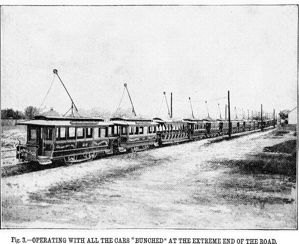
The accompanying illustrations will aid in understanding the description. Figs 1, 2 and 3 are views taken upon the Richmond Union Passenger Railway Company's line, and need no further reference. Fig. 4 is an enlarged view of one of the Sprague motor cars, exhibiting the position of the operative mechanism, and of the contact trolley.
Fig. 5 is a view of a new and improved clectric motor truck, lately devised by the Sprague Electric Railway & Motor Co. for all their street railway work. They call this design the "Boston," to distinguish it from the old-style, which they call the "Richmond."
Great care has been taken in the construction of every part of this truck to make it as strong and light as possible, and many new improvements have been introduced to meet the exigencies of streetcar service.
All the bearings are self-oiling and dustproof. By looking carefully at the illustation (Fig. 5), there may be noticed projections extending below the axle. These projections are hollow, filled with oil, and in this oil there is a spring which presses prepared felt against the axle, thus insuring perfect lubrication. This method has been tried with great success in street-car work, and should run at least a month with little or no attention.
The next set of bearings is that which sustains the intermediate shaft, which passes between the fields. These bearings are also made self-oiling and dust-proof. The teeth to this intermediate gear are made of vulcanized fiber which is perfectly noiseless, and is so constructed that it will out-wear amy steel gearing ever made. All these gears and pinions are independently removable, and the whole arrangement is such, that the bearings and gears can be removed and changed, if necessary, witimout dismounting the machine.
The motors are of new design and of superior workmanship and construction. They are built in two sizes, of 7 1/2 and 15 horse-power capacity each, and are identical in general appearance. They are adapted to be applied to standard cars or to special trucks.
The motors have the regular Sprague mounting, being centered on the axles, and flexibly supported. This flexible support is arranged for both directions for driving, so that there is always a spring attachment, which will prevent any rattling and will also relieve the machinery of any sudden strain. Without this flexible suspension, for both directions of running, it is hard to imagine how a motor can be successfully applied to street-cars and fulfill all conditions of actual experience.
The brushes are of entirely new principle and design, and are remarkable for ease of adjustment, and work with equal facility in running either forward or backwards.
A tight fitting cover, moving with the machine, encloses all the apparatus, rendering it impossible for moisture or dust to get into the working parts.
The design in the construction of this motor and truck has been not only to make the machine very strong and readily accessible, but also to reduce all necessary attedance and cares to a minimun.
The Sprague Company may be congratulated upon the completion of a machine which combines so well the essential qualifications for a street-railway truck, and we anticipate for them a great success in electric street railway propulsion in the futute.

|
FIG. 2 CAR ON STEEP GRADE, RICHMOND VA., ROAD. |
|
FIG. 3 OPERATING WITH ALL THE CARS "BUNCHED" AT THE EXTREME END OF THE ROAD. |

|
FIG. 4 SPRAGUE ELECTRIC RAILWAY MOTOR CAR. |
|
|
FIG. 5 SPRAGUE IMPROVED ELECTRIC MOTOR TRUCK. |
A bonus magazine ad for the Sprague Electric Railway and Motor Company. Scribner's Magazine, Volume 5, Number 6, June, 1889, page 69.

|
Go to top of page.